POWER OUTER MIRROR INSPECTION
POWER OUTER MIRROR INSPECTION
SM2336371
id091200002700
1.Disconnect the negative battery terminal. (See NEGATIVE BATTERY TERMINAL DISCONNECTION/CONNECTION [(US)].)
2.Remove the power outer mirror. (See POWER OUTER MIRROR REMOVAL/INSTALLATION.)
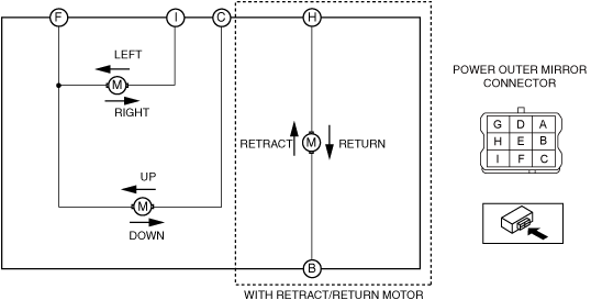
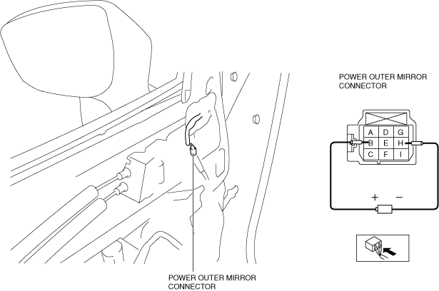
3.Apply battery positive voltage and connect the ground to the power outer mirror terminals and inspect the power outer mirror operation.
am3zzw00034862
|
-
• If the power outer mirror does not operate as indicated in the table, replace the power outer mirror.
|
Mirror operation direction |
Battery positive voltage connect terminal |
Ground connect terminal |
|---|---|---|
|
Up
|
C
|
F
|
|
Down
|
F
|
C
|
|
Left
|
I
|
F
|
|
Right
|
F
|
I
|
|
Retract
|
B
|
H
|
|
Return
|
H
|
B
|
Heated Outer Mirror Inspection
1.Disconnect the negative battery terminal. (See NEGATIVE BATTERY TERMINAL DISCONNECTION/CONNECTION [(US)].)
2.Remove the outer mirror glass. (See OUTER MIRROR GLASS REMOVAL.) (See OUTER MIRROR GLASS INSTALLATION.)
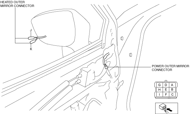
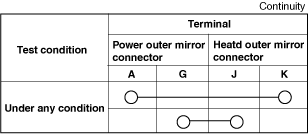
3.Verify that the continuity between heated outer mirror connector terminals is as indicated in the table.
am3zzw00034863
|
-
• If not as indicated in the table, replace the power outer mirror. (See POWER OUTER MIRROR REMOVAL/INSTALLATION.)
 ac5uuw00003737
Blind Spot Monitoring (BSM) Warning Indicator Light Inspection
1.Disconnect the negative battery terminal. (See NEGATIVE BATTERY TERMINAL DISCONNECTION/CONNECTION [(US)].)
2.Remove the outer mirror glass. (See OUTER MIRROR GLASS REMOVAL.) (See OUTER MIRROR GLASS INSTALLATION.)
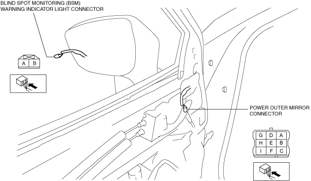
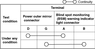
3.Verify that the continuity between blind spot monitoring (BSM) warning indicator light connector terminals is as indicated in the table.
am3zzw00034864
|
-
• If not as indicated in the table, replace the power outer mirror. (See POWER OUTER MIRROR REMOVAL/INSTALLATION.)am3zzw00027423
Auto-dimming Outer Mirror Inspection
1.Disconnect the negative battery terminal. (See NEGATIVE BATTERY TERMINAL DISCONNECTION/CONNECTION [(US)].)
2.Remove the outer mirror glass. (See OUTER MIRROR GLASS REMOVAL.) (See OUTER MIRROR GLASS INSTALLATION.)
3.Disconnect the power outer mirror connector.
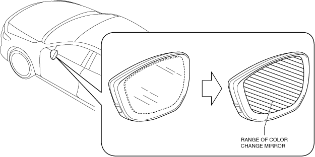
4.Connect the power outer mirror connector terminal B to a dry cell battery’s plus (+) terminal (1.2 V) and terminal H to its minus terminal.
amxuuw00004178
|
-
• Verify that the mirror side of the outer mirror glass changes color.am3zzw00030500
5.If there is any malfunction, inspect the outer mirror glass. (See OUTER MIRROR GLASS INSPECTION.)
-
• If there is no malfunction in the outer mirror glass, replace the power outer mirror. (See POWER OUTER MIRROR REMOVAL/INSTALLATION.)