REAR BUMPER DISASSEMBLY/ASSEMBLY [(US)]
REAR BUMPER DISASSEMBLY/ASSEMBLY [(US)]
SM2763805
id0910008008x1
Special Service Tool (SST)
|
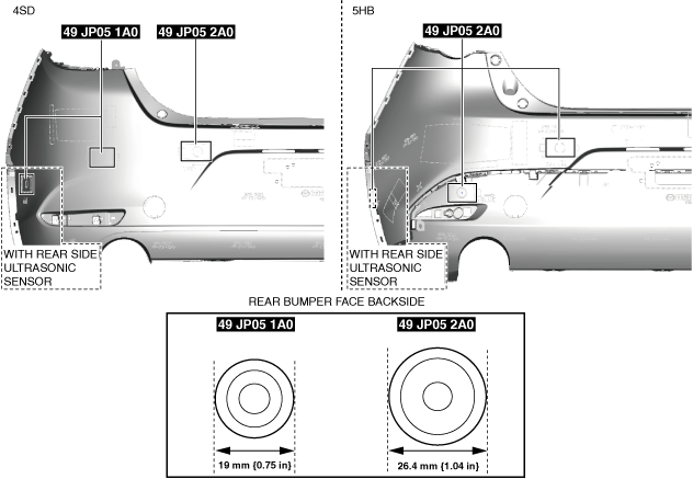
49 JP05 1A0
HOLE CUTTER SET 19 (Part of 49 JP05 0A0)
|
 |
49 JP05 2A0
HOLE CUTTER SET 26 (Part of 49 JP05 0A0)
|
 |
Replacement part
|
Set plate
Quantity: 2
Location of use: Rear bumper face
|
Retainer bracket (with rear ultrasonic sensor (with rear side ultrasonic sensor))
Quantity: 6
Location of use: Rear bumper face
|
Retainer bracket (with rear ultrasonic sensor (without rear side ultrasonic sensor))
Quantity: 4
Location of use: Rear bumper face
|
1.Remove the following parts:
- (1)License plate light short-cord (See LICENSE PLATE LIGHT SHORT-CORD REMOVAL/INSTALLATION.)
- (2)License plate light (See LICENSE PLATE LIGHT REMOVAL/INSTALLATION.)
- (3)Rear mount camera (with rear mount camera) (See REAR MOUNT CAMERA REMOVAL/INSTALLATION.)
- (4)Rear ultrasonic sensor (with rear ultrasonic sensor) (See REAR ULTRASONIC SENSOR REMOVAL/INSTALLATION.)
- (5)Retainer (with rear ultrasonic sensor) (See REAR ULTRASONIC SENSOR REMOVAL/INSTALLATION.)
- (6)Retainer bracket (with rear ultrasonic sensor) (See REAR ULTRASONIC SENSOR REMOVAL/INSTALLATION.)
- (7)Rear side radar sensor (with rear side radar sensor) (See REAR SIDE RADAR SENSOR REMOVAL/INSTALLATION.)
2.Disassemble in the order indicated in the table.
-
Warning
-
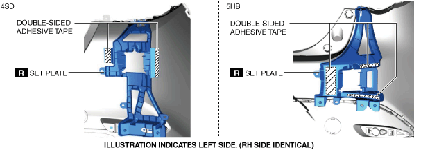
• When removing the set plate, peel off the double-sided adhesive tape at the positions shown in the figure using a utility knife. Always wear gloves when using a utility knife. Using a utility knife with bare hands can cause injury.
 am3zzw00023202
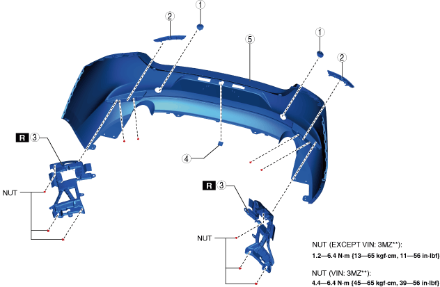
4SD
am3zzw00033036
|
|
1
|
Towing hook cover
|
|
2
|
Rear reflector
|
|
3
|
Set plate
(See Set Plate Installation Note.)
|
|
4
|
Cap (without rear mount camera)
|
|
5
|
Rear bumper face
|
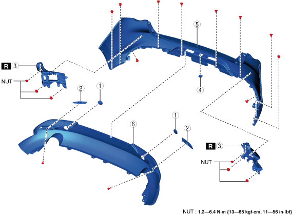
5HB
am3zzw00033037
|
|
1
|
Towing hook cover
|
|
2
|
Rear reflector
|
|
3
|
Set plate
(See Set Plate Installation Note.)
|
|
4
|
Cap (without rear mount camera)
|
|
5
|
Rear bumper face No.1
|
|
6
|
Rear bumper face No.2
|
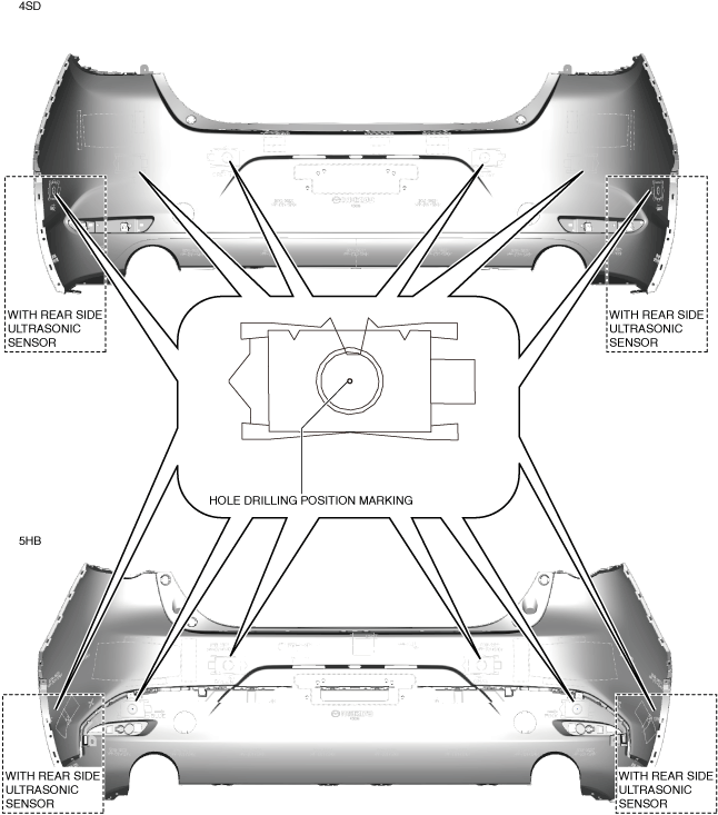
3.When replacing the rear bumper face with a new one, perform the following procedure (With rear ultrasonic sensor):
- (1)Paint the rear bumper.
- (2)Drill the holes in the position shown in the figure.
-
- Drill hole diameter: 10 mm {0.39 in}
am3zzw00033038-
Caution
-
• There are two types of SSTs. Before drilling the rear bumper face using an SST, verify the shape of the SST.am3zzw00036292• If the SST is pulled out to the front side of the rear bumper face, the painting could peel off. Pull out the SST to the backside of the rear bumper face.
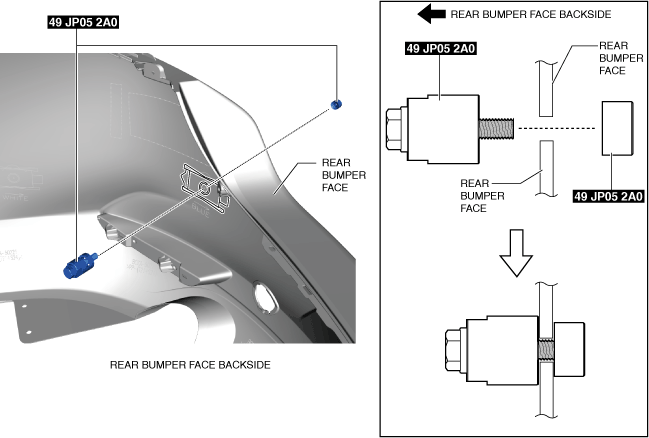
- (3)Set the SST to the positions shown in the figure.
-
am3zzw00036848
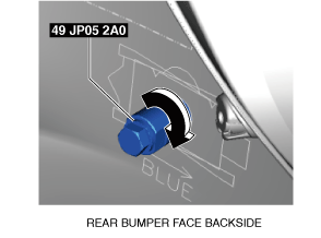
- (4)Tighten the bolt of the SST in the direction of the arrow shown in the figure and pass it through the rear bumper face.
-
am3zzw00036849
- (5)Drill a hole at the remaining ultrasonic sensor installation position using the SST and the same method as Steps 3 and 4.
- (6)Remove burrs from the drilled holes.
- (7)Remove any grease or dirt from the retainer bracket installation surface of the rear bumper face.
-
am3zzw00033042
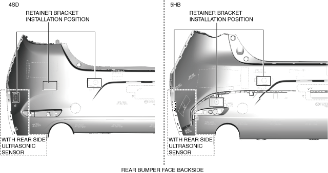
- (8)Apply primer to the retainer bracket installation surface of the rear bumper face.
- (9)Peel off the backing of the double-sided adhesive tape and install the retainer bracket.
-
am3zzw00033043
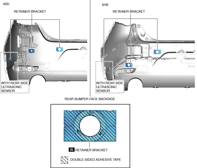
- (10)Press the retainer bracket to adhere the double-sided adhesive tape.
4.Assemble in the reverse order of disassembly.
Set Plate Installation Note
1.Remove any grease or dirt from the set plate installation surface of the rear bumper face.
am3zzw00023205
|
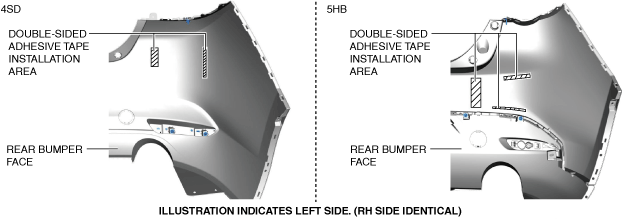
2.Peel off the backing of the double-sided adhesive tape and install the set plate.
am3zzw00023202
|
3.Press the set plate to adhere the double-sided adhesive tape.