PUSH BUTTON START SYSTEM DOES NOT OPERATE [SECURITY AND LOCKS]
PUSH BUTTON START SYSTEM DOES NOT OPERATE [SECURITY AND LOCKS]
SM2336288
id0903k7023500
Outline
|
Description
|
• When the push button start is pressed, the ignition cannot be switched to ACC or ON (engine off).
|
|
|
Possible cause
|
• Connector or terminal malfunction of the following parts:
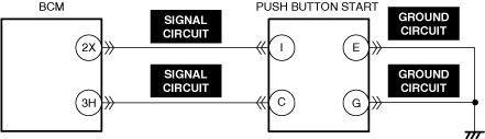
• Short to power supply, short to ground, or open circuit in push button start signal circuit
• Short to power supply or open circuit in push button start ground circuit
• Push button start malfunction
• BCM malfunction
|
|
 |
||
 |
 |
|
Diagnostic Procedure
|
Step |
Inspection |
Results |
Action |
|---|---|---|---|
|
1
|
VERIFY ALL SYSTEM DTCs
• Perform the DTC inspection. (See DTC INSPECTION.)
• Are any DTCs displayed?
|
Yes
|
Repair the malfunctioning location according to the applicable DTC troubleshooting.
|
|
No
|
Go to the next step.
|
||
|
2
|
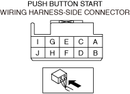
INSPECT PUSH BUTTON START AND BCM CONNECTORS FOR MALFUNCTION
• Inspect the applicable connector and terminal. (See CONNECTOR INSPECTION.)
• Are the connector and terminal normal?
|
Yes
|
Go to the next step.
|
|
No
|
Repair or replace the malfunctioning location and perform the repair completion verification.
|
||
|
3
|
INSPECT PUSH BUTTON START SIGNAL CIRCUIT FOR SHORT TO POWER SUPPLY, SHORT TO GROUND, AND OPEN CIRCUIT
• Inspect the signal circuit for a short to power supply, short to ground, and an open circuit. (See CIRCUIT INSPECTION.)
• Is the circuit normal?
|
Yes
|
Go to the next step.
|
|
No
|
Repair or replace the malfunctioning location and perform the repair completion verification.
|
||
|
4
|
INSPECT PUSH BUTTON START GROUND CIRCUIT FOR SHORT TO POWER SUPPLY AND OPEN CIRCUIT
• Inspect the ground circuit for a short to power supply and an open circuit. (See CIRCUIT INSPECTION.)
• Is the circuit normal?
|
Yes
|
Go to the next step.
|
|
No
|
Repair or replace the malfunctioning location and perform the repair completion verification.
|
||
|
5
|
INSPECT PUSH BUTTON START FOR MALFUNCTION
• Inspect the applicable part. (See PUSH BUTTON START INSPECTION.)
• Is the part normal?
|
Yes
|
Go to the next step.
|
|
No
|
Repair or replace the malfunctioning location and perform the repair completion verification.
|
||
|
Repair completion verification
|
VERIFY THAT VEHICLE IS REPAIRED
• Install/connect the part removed/disconnected during the troubleshooting procedure.
• Has the malfunction symptom been eliminated?
|
Yes
|
Complete the symptom troubleshooting. (Explain contents of repair to customer)
|
|
No
|
Refer to the controller area network (CAN) malfunction diagnosis flow to inspect for a CAN communication error.
If the CAN communication is normal, perform the diagnosis from Step 1.
• If the malfunction is not resolved, replace the BCM. (See BODY CONTROL MODULE (BCM) REMOVAL/INSTALLATION.)
|