SHIFT-LOCK SOLENOID INSPECTION
SHIFT-LOCK SOLENOID INSPECTION
SM2335502
id051800298100
-
Note
-
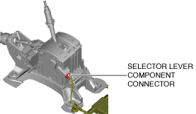
• The shift-lock solenoid is built into the selector lever component.
1.Disconnect the negative battery terminal. (See NEGATIVE BATTERY TERMINAL DISCONNECTION/CONNECTION [(US)].)
2.Remove the following parts:
- (1)Selector lever knob (See SELECTOR LEVER COMPONENT REMOVAL/INSTALLATION.)
- (2)Shift panel (See SHIFT PANEL REMOVAL/INSTALLATION.)
- (3)Front console box (See FRONT CONSOLE BOX REMOVAL/INSTALLATION.)
- (4)Cup holder (See CUP HOLDER REMOVAL/INSTALLATION.)
- (5)Side wall (See SIDE WALL REMOVAL/INSTALLATION.)
- (6)Rear console (See REAR CONSOLE REMOVAL/INSTALLATION [(US)].)
- (7)Rear console bracket No.1 (See REAR CONSOLE REMOVAL/INSTALLATION [(US)].)
3.Reconnect the negative battery terminal. (See NEGATIVE BATTERY TERMINAL DISCONNECTION/CONNECTION [(US)].)
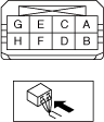
4.Verify that the voltages of each of the selector lever component terminals are as indicated in the table.
am3zzw00021700
|
am3zzw00034748
|
Standard
|
Terminal |
Connected to |
Test condition |
Voltage (V) |
|---|---|---|---|
|
A
|
IG1 relay No.2
|
Ignition switched ON (engine on)
|
B+
|
|
Except above
|
Below 1.0
|
||
|
E
|
Shift panel indicator
|
The following conditions are met (except emergency manual shift-lock release system is operated)
― Selector lever is in P position
― Ignition is switched to ON
― Brake pedal is depressed (brake light switch is on)
|
Below 1.0
|
|
Except above
|
B+
|
-
• If the voltage is not as indicated in the table, repair or replace the related wiring harness.
-
― If the related wiring harnesses are normal, replace the selector lever component. (See SELECTOR LEVER COMPONENT REMOVAL/INSTALLATION.)
-