SELECTOR CABLE REMOVAL/INSTALLATION [(US)]
SELECTOR CABLE REMOVAL/INSTALLATION [(US)]
SM2335501
id0518002977x1
1.Disconnect the negative battery terminal. (See NEGATIVE BATTERY TERMINAL DISCONNECTION/CONNECTION [(US)].)
2.Perform the following procedure to remove the selector cable (transaxle side).
- (1)Remove the following parts as a single unit. (See INTAKE-AIR SYSTEM REMOVAL/INSTALLATION [SKYACTIV-G (WITHOUT CYLINDER DEACTIVATION (US))].) (See INTAKE-AIR SYSTEM REMOVAL/INSTALLATION [SKYACTIV-G (WITH CYLINDER DEACTIVATION (US))].)
-
-
• Air cleaner cover• Air cleaner element• Fresh-air duct• Air cleaner case• Air hose• Resonance chamber
-
- (2)Remove the battery. (See BATTERY REMOVAL/INSTALLATION [SKYACTIV-G (WITHOUT CYLINDER DEACTIVATION (US))].) (See BATTERY REMOVAL/INSTALLATION [SKYACTIV-G (WITH CYLINDER DEACTIVATION (US))].)
- (3)Remove the battery tray and PCM component as a single unit. (See BATTERY REMOVAL/INSTALLATION [SKYACTIV-G (WITHOUT CYLINDER DEACTIVATION (US))].) (See BATTERY REMOVAL/INSTALLATION [SKYACTIV-G (WITH CYLINDER DEACTIVATION (US))].)
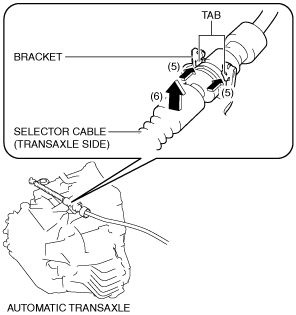
- (4)While pressing the bracket tab in the direction of the arrow (5) shown in the figure, lift up the cable outer end (transaxle side) in the direction of the arrow (6) shown in the figure to detach the bracket tab from the cable outer end (transaxle side).
-
 am6xuw00009728
- (5)Disconnect the cable outer end (transaxle side) from the bracket. (See Cable Outer End (Transaxle Side) Installation Note.)
- (6)Disconnect the clip from the selector cable end (transaxle side). (See Selector Cable End (Transaxle Side) Installation Note.)
-
-
Caution
-
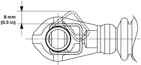
• Pull the clip within the range shown in the figure. If the clip is pulled excessively, it could deform and no longer function.ac5uuw00009245
am6xuw00009729 -
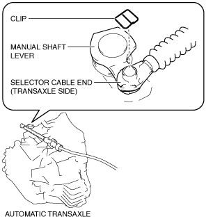
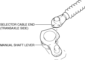
- (7)Disconnect the selector cable end (transaxle side) from the manual shaft lever.
-
am6xuw00009730
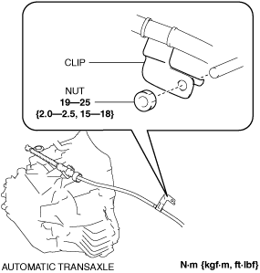
3.Disconnect the clip as shown in the figure and remove the nut.
am6xuw00009731
|
4.Perform the following procedure to remove the selector cable (selector lever side).
- (1)Remove the selector lever knob. (See SELECTOR LEVER COMPONENT REMOVAL/INSTALLATION.)
- (2)Remove the shift panel. (See SHIFT PANEL REMOVAL/INSTALLATION.)
- (3)Remove the front console box. (See FRONT CONSOLE BOX REMOVAL/INSTALLATION.)
- (4)Remove the cup holder. (See CUP HOLDER REMOVAL/INSTALLATION.)
- (5)Remove the side wall. (See SIDE WALL REMOVAL/INSTALLATION.)
- (6)Remove the rear console. (See REAR CONSOLE REMOVAL/INSTALLATION [(US)].)
- (7)Remove the rear console bracket No.1. (See REAR CONSOLE REMOVAL/INSTALLATION [(US)].)
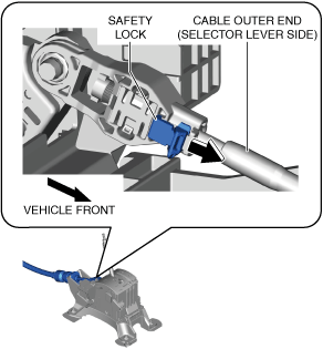
- (8)Move the safety lock in the direction of the arrow shown in the figure and release the safety lock.
-
am3zzw00027367
- (9)Press the tabs of the adjuster case shown in the figure in the directions of arrows (1) shown in the figure.
-
am3zzw00027368
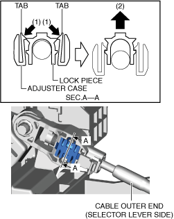
- (10)Press out the lock piece in the direction of arrow (2) shown in the figure and release the lock. (See Selector Cable (Selector Lever Side) Installation Note.)
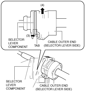
- (11)While pressing the cable outer end tab (selector lever side) in the direction of the arrow (3) shown in the figure, lift up cable outer end (selector lever side) in the direction of the arrow (4) shown in the figure to detach the cable outer end tab (selector lever side) from the selector lever component.
-
am6xuw00009725
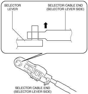
- (12)Disconnect the cable outer end (selector lever side) from the selector lever component.
- (13)Disconnect the selector cable end (selector lever side) from the selector lever.
-
am6xuw00009726
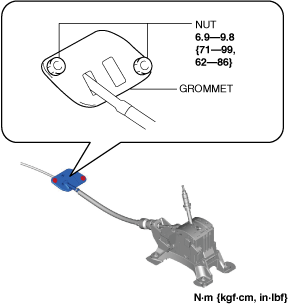
5.Disconnect the grommet as shown in the figure and remove the nuts.
am3zzw00021705
|
6.Pull out the selector cable from inside the cabin and remove it.
7.Install in the reverse order of removal.
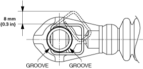
Selector Cable End (Transaxle Side) Installation Note
1.Install a clip to the groove of the selector cable end (transaxle side).
-
Caution
-
• Pull the clip within the range shown in the figure. If the clip is pulled excessively, it could deform and no longer function.ac5uuw00009246
Cable Outer End (Transaxle Side) Installation Note
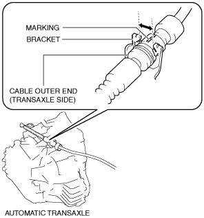
1.Assemble the cable outer end (transaxle side) to the bracket so that the marking is in the area of the arrow shown in the figure.
am6xuw00009732
|
Selector Cable (Selector Lever Side) Installation Note
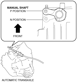
1.Verify that the selector lever is in the P position.
2.Verify that the manual shaft is in the P position.
am3uuw00011063
|
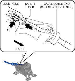
3.Press in the lock piece in the direction of the arrow (1) shown in the figure, press in the safety lock in the direction of the arrow (2) shown in the figure, and lock it.
am3zzw00021706
|