DTC C0023:62 [DSC HU/CM]
DTC C0023:62 [DSC HU/CM]
SM2335028
id040262003500
Outline
|
System malfunction location |
Brake light |
||||
|---|---|---|---|---|---|
|
Detection condition
|
• The DSC HU/CM detects any of the following conditions.
|
||||
|
Fail-safe
|
Refer to “DTC Table” and “Fail-safe Function Malfunction Contents Table”. (See DTC TABLE [DSC HU/CM (US)].)
|
||||
|
Possible cause
|
• DTCs are stored in the body control module (BCM).
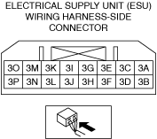
• Electrical supply unit (ESU) connector or terminals malfunction
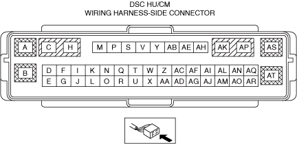
• DSC HU/CM connector or terminals malfunction
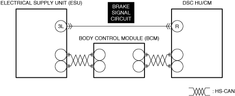
• Short to ground in electrical supply unit (ESU) brake signal circuit
• Short to power supply in electrical supply unit (ESU) brake signal circuit
• Open circuit in electrical supply unit (ESU) brake signal circuit
• Electrical supply unit (ESU) malfunction
• DSC HU/CM malfunction
|
||||
 |
|||||
 |
|||||
 |
|||||
Diagnostic Procedure
|
Step |
Inspection |
Results |
Action |
|---|---|---|---|
|
1
|
INSPECT BODY CONTROL MODULE (BCM) FOR MALFUNCTION
• Perform the DTC inspection for the body control module (BCM). (See DTC INSPECTION.)
• Are any DTCs displayed?
|
Yes
|
Repair the malfunctioning location according to the applicable DTC troubleshooting.
|
|
No
|
Go to the next step.
|
||
|
2
|
INSPECT ELECTRICAL SUPPLY UNIT (ESU) CONNECTOR FOR MALFUNCTION
• Inspect the applicable connector and terminal. (See CONNECTOR INSPECTION.)
• Are the connector and terminal normal?
|
Yes
|
Go to the next step.
|
|
No
|
Repair or replace the malfunctioning location and perform the repair completion verification.
|
||
|
3
|
INSPECT DSC HU/CM CONNECTOR FOR MALFUNCTION
• Inspect the applicable connector and terminal. (See CONNECTOR INSPECTION.)
• Are the connector and terminal normal?
|
Yes
|
Go to the next step.
|
|
No
|
Repair or replace the malfunctioning location and perform the repair completion verification.
|
||
|
4
|
INSPECT ELECTRICAL SUPPLY UNIT (ESU) BRAKE SIGNAL CIRCUIT FOR SHORT TO GROUND
• Inspect the applicable circuit for a short to ground. (See CIRCUIT INSPECTION.)
• Is the circuit normal?
|
Yes
|
Go to the next step.
|
|
No
|
Repair or replace the malfunctioning location and perform the repair completion verification.
|
||
|
5
|
INSPECT ELECTRICAL SUPPLY UNIT (ESU) BRAKE SIGNAL CIRCUIT FOR SHORT TO POWER SUPPLY
• Inspect the applicable circuit for a short to power supply. (See CIRCUIT INSPECTION.)
• Is the circuit normal?
|
Yes
|
Go to the next step.
|
|
No
|
Repair or replace the malfunctioning location and perform the repair completion verification.
|
||
|
6
|
INSPECT ELECTRICAL SUPPLY UNIT (ESU) BRAKE SIGNAL CIRCUIT FOR OPEN CIRCUIT
• Inspect the applicable circuit for open circuit. (See CIRCUIT INSPECTION.)
• Is the circuit normal?
|
Yes
|
Go to the next step.
|
|
No
|
Repair or replace the malfunctioning location and perform the repair completion verification.
|
||
|
7
|
INSPECT ELECTRICAL SUPPLY UNIT (ESU) FOR MALFUNCTION
• Install/connect the part removed/disconnected during the troubleshooting procedure.
• Measure the voltage at electrical supply unit (ESU) terminal 3L (vehicle wiring harness side) according to the brake pedal operation and verify if it changes as follows.
• Does the voltage change according to the brake pedal operation?
|
Yes
|
Go to the next step.
|
|
No
|
Repair or replace the malfunctioning location and perform the repair completion verification.
|
||
|
Repair completion verification 1
|
VERIFY THAT VEHICLE IS REPAIRED
• Install/connect the part removed/disconnected during the troubleshooting procedure.
• Clear the DTC recorded in the memory. (See CLEARING DTC.)
• Perform the work of depressing the brake pedal for 3 s or more and then releasing it for 5 times or more with the ignition switched ON (engine off or on).
• Perform the DTC inspection for the DSC HU/CM. (See DTC INSPECTION.)
• Is the same Pending DTC present?
|
Yes
|
Refer to the controller area network (CAN) malfunction diagnosis flow to inspect for a CAN communication error.
If the CAN communication is normal, perform the diagnosis from Step 1.
• If the malfunction recurs, replace the DSC HU/CM, then go to the next step. (See DSC HU/CM REMOVAL/INSTALLATION [L.H.D. (US)].)
|
|
No
|
Go to the next step.
|
||
|
Repair completion verification 2
|
VERIFY IF OTHER DTCs DISPLAYED
• Perform the DTC inspection. (See DTC INSPECTION.)
• Are any DTCs displayed?
|
Yes
|
Repair the malfunctioning location according to the applicable DTC troubleshooting.
|
|
No
|
DTC troubleshooting completed.
|