DTC C0020:11, C0020:12, C0020:13, C0020:49 OR C0020:71 [DSC HU/CM]
DTC C0020:11, C0020:12, C0020:13, C0020:49 OR C0020:71 [DSC HU/CM]
SM2335026
id040262003300
Outline
|
System malfunction location |
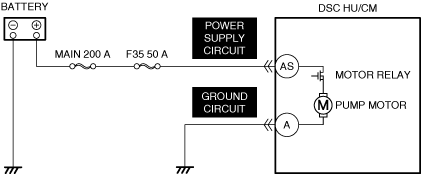
Pump motor, pump relay |
||||
|---|---|---|---|---|---|
|
Detection condition
|
• C0020:11
• C0020:12
• C0020:13
• C0020:49
• C0020:71
|
||||
|
Fail-safe
|
Refer to “DTC Table” and “Fail-safe Function Malfunction Contents Table”. (See DTC TABLE [DSC HU/CM (US)].)
|
||||
|
Possible cause
|
• DSC HU/CM connector or terminals malfunction
• Short to ground or open circuit in DSC HU/CM power supply circuit
• Open circuit in DSC HU/CM ground circuit
• DSC HU/CM malfunction
|
||||
 |
|||||
 |
|||||
Diagnostic Procedure
|
Step |
Inspection |
Results |
Action |
|---|---|---|---|
|
1
|
VERIFY PUMP MOTOR OPERATION
• Verify if the pump motor operates using the simulation item TCS_PUMP_MOTOR. (See SIMULATION INSPECTION.) (See SIMULATION TABLE [DSC HU/CM].)
• Does the pump motor operate?
|
Yes
|
Perform the repair completion verification.
|
|
No
|
Go to the next step.
|
||
|
2
|
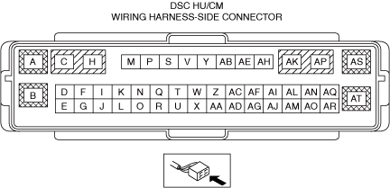
INSPECT DSC HU/CM CONNECTOR FOR MALFUNCTION
• Inspect the applicable connector and terminal. (See CONNECTOR INSPECTION.)
• Are the connector and terminal normal?
|
Yes
|
Go to the next step.
|
|
No
|
Repair or replace the malfunctioning location and perform the repair completion verification.
|
||
|
3
|
INSPECT DSC HU/CM POWER SUPPLY CIRCUIT FOR SHORT TO GROUND AND OPEN CIRCUIT
• Inspect the power supply circuit for an open circuit and short to ground. (See CIRCUIT INSPECTION.)
• Is the circuit normal?
|
Yes
|
Go to the next step.
|
|
No
|
Repair or replace the malfunctioning location and perform the repair completion verification.
|
||
|
4
|
INSPECT DSC HU/CM POWER SUPPLY CIRCUIT FOR SHORT TO POWER SUPPLY
• Inspect the applicable circuit for a short to power supply. (See CIRCUIT INSPECTION.)
• Is the circuit normal?
|
Yes
|
Go to the next step.
|
|
No
|
Repair or replace the malfunctioning location and perform the repair completion verification.
|
||
|
5
|
INSPECT DSC HU/CM GROUND CIRCUIT FOR OPEN CIRCUIT
• Inspect the applicable circuit for open circuit. (See CIRCUIT INSPECTION.)
• Is the circuit normal?
|
Yes
|
Go to the next step.
|
|
No
|
Repair or replace the malfunctioning location and perform the repair completion verification.
|
||
|
Repair completion verification 1
|
VERIFY THAT VEHICLE IS REPAIRED
• Install/connect the part removed/disconnected during the troubleshooting procedure.
• Clear the DTC recorded in the memory. (See CLEARING DTC.)
• Start the engine and drive the vehicle at 10 km/h {6.2 mph} or more.
• Perform the DTC inspection for the DSC HU/CM. (See DTC INSPECTION.)
• Is the same Pending DTC present?
|
Yes
|
Refer to the controller area network (CAN) malfunction diagnosis flow to inspect for a CAN communication error.
If the CAN communication is normal, perform the diagnosis from Step 1.
• If the malfunction recurs, replace the DSC HU/CM, then go to the next step. (See DSC HU/CM REMOVAL/INSTALLATION [L.H.D. (US)].)
|
|
No
|
Go to the next step.
|
||
|
Repair completion verification 2
|
VERIFY IF OTHER DTCs DISPLAYED
• Perform the DTC inspection. (See DTC INSPECTION.)
• Are any DTCs displayed?
|
Yes
|
Repair the malfunctioning location according to the applicable DTC troubleshooting.
|
|
No
|
DTC troubleshooting completed.
|