FRONT DRIVE SHAFT (TRIPOD JOINT) DISASSEMBLY/ASSEMBLY [(US)]
FRONT DRIVE SHAFT (TRIPOD JOINT) DISASSEMBLY/ASSEMBLY [(US)]
SM2335020
id0313008026y1
Special service tool (SST)
|
49 H027 002
Bearing remover
|
 |
49 W032 310
Support block
|
 |
49 T025 001
Boot clamp crimpers
|
 |
|
49 UB71 525
Bearing installer
|
 |
49 0710 520
Bearing puller
|
 |
—
|
|
Replacement part
|
Boot band (transaxle side)
Quantity: 2
Location of use: Boot (transaxle side)
|
Dust cover
Quantity: 1
Location of use: Outer ring
|
Snap ring
Quantity: 1
Location of use: Outer ring
|
|
Clip
Quantity: 1
Location of use: Outer ring
|
Bearing
Quantity: 1
Location of use: Outer ring
|
Snap ring
Quantity: 1
Location of use: Tripod joint
|
|
Boot (transaxle side)
Quantity: 1
Location of use: Front drive shaft (transaxle side)
|
Boot band (wheel side)
Quantity: 2
Location of use: Boot (wheel side)
|
Boot (wheel side)
Quantity: 1
Location of use: Front drive shaft (wheel side)
|
Oil and chemical type
|
Grease
Type: Maintenance parts
|
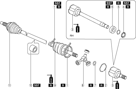
1.Disassemble in the order shown in the figure.
2.Assemble in the reverse order of disassembly.
ATX
am3zzw00034689
|

|
1
|
Boot band (transaxle side)
|
|
2
|
Clip (With clip)
|
|
3
|
Outer ring
|
|
4
|
Dust cover (With dust cover)
(See Dust Cover Disassembly Note.)
(See Dust Cover Assembly Note.)
|
|
5
|
Snap ring
|
|
6
|
Bearing
(See Bearing Disassembly Note.)
(See Bearing Assembly Note.)
|
|
7
|
Snap ring
|
|
8
|
Tripod joint
|
|
9
|
Boot (transaxle side)
|
|
10
|
Boot band (wheel side)
|
|
11
|
Boot (wheel side)
|
|
12
|
Shaft and ball joint component
|
|
13
|
Outer joint component
|
MTX
am3zzw00023110
|
|
1
|
Boot band (transaxle side)
|
|
2
|
Clip (With clip)
|
|
3
|
Outer ring
|
|
4
|
Dust cover
(See Dust Cover Disassembly Note.)
(See Dust Cover Assembly Note.)
|
|
5
|
Snap ring
|
|
6
|
Bearing
(See Bearing Disassembly Note.)
(See Bearing Assembly Note.)
|
|
7
|
Snap ring
|
|
8
|
Tripod joint
|
|
9
|
Boot (transaxle side)
|
|
10
|
Dynamic damper
|
|
11
|
Outer joint component
|
Boot Band (Transaxle Side) Disassembly Note (VIN: JM*)
1.Using a flat chisel and hammer, lightly tap the lever of the boot band to disconnect the lock clip.
ac8wzw00002085
|
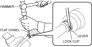
2.Remove the boot band using pliers.
ac8wzw00002086
|
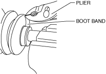
Boot Band (Transaxle Side) Disassembly Note (VIN: 3M*)
Large diameter side
1.Grasp the boot band at the point shown in the figure using pliers, and remove the band.
ac5jjw00003246
|
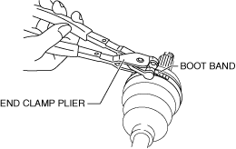
Small diameter side
1.Remove the boot band using end clamp pliers.
aatjjw00009759
|
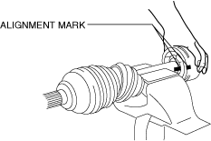
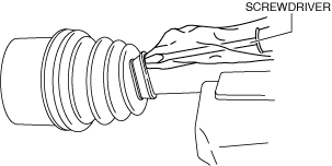
Clip, Outer Ring Disassembly Note
-
Caution
-
• To prevent part damage, do not use a punch or similar tool to place alignment marks. Use paint.
1.Place alignment marks on the shaft and outer ring.
am3zzw00036341
|
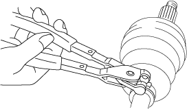
2.Remove the clip using a screwdriver. (With clip)
am3zzw00023111
|

3.Remove the outer ring from the shaft.
4.Wipe off grease on the outer ring using a clean cloth.
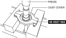
Dust Cover Disassembly Note
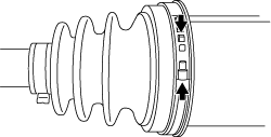
1.Remove the dust cover using a press and the SST.
ac8wzw00002089
|
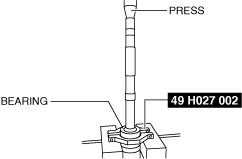
Bearing Disassembly Note
1.Remove the bearing using a press and the SST.
ac8wzw00002090
|
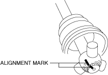
Snap Ring, Tripod Joint Disassembly Note
-
Caution
-
• To prevent damage to parts, use paint instead of a punch or similar tool to place alignment marks.
1.Place alignment marks on the shaft and tripod joint.
ac8wzw00002091
|
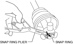
2.Remove the snap ring using snap ring pliers.
ac8wzw00002092
|
-
Note
-
• If the tripod joint cannot be removed from the shaft, lightly tap the tripod joint evenly using a hammer and urethane bar or equivalent, and remove the tripod joint from the shaft.
-
Caution
-
• Be careful not to scratch the roller area when using a hammer and urethane bar or equivalent. Otherwise, the part could be damaged.
3.Remove the tripod joint from the shaft.
4.Wipe off grease on the shaft and tripod joint using a clean cloth.
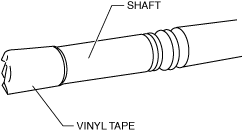
Boot (Transaxle Side) Disassembly Note
1.Wrap vinyl tape around the spline area of the shaft to prevent damage to the boot.
ac8wzw00002093
|
2.Remove the boot (transaxle side).
3.Wipe off grease on the boot (transaxle side) using a clean cloth.
Boot Band (Wheel Side) Disassembly Note
1.Remove the boot band using end clamp pliers.
ac8wzw00002094
|
Boot (Wheel Side) Disassembly Note
1.Wrap vinyl tape around the spline area of the shaft to prevent damage to the boot.
ac8wzw00002093
|
2.Remove the boot (wheel side).
3.Wipe off grease on the boot (wheel side) and ball joint using a clean cloth.
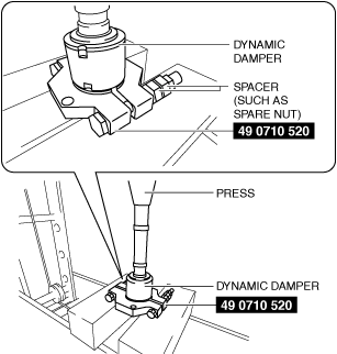
Dynamic Damper Disassembly Note [MTX]
1.Remove the dynamic damper using the SST, spacers (such as spare nuts), and a press.
am2zzw00007267
|
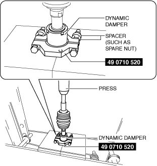
Dynamic Damper Assembly Note [MTX]
1.Apply soapy water to the inside of the dynamic damper.
2.Assemble the dynamic damper using the SST, spacers (such as spare nuts), and a press.
am6xuw00011607
|
3.Verify that the installation position of the dynamic damper is within the specification.
am2zzw00007269
|
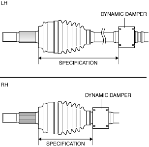
Specification [Except Mexico]
|
Engine type |
Installation position |
|
|---|---|---|
|
SKYACTIV-G 2.0
|
LH
|
281.6—286.6 mm {11.09—11.28 in}
|
|
SKYACTIV-G 2.5
|
LH
|
280.9—286.9 mm {11.06—11.29 in}
|
Specification [Mexico]
|
Engine type |
Installation position |
|
|---|---|---|
|
SKYACTIV-G 2.0
|
LH
|
275.5—281.5 mm {10.85—11.08 in}
|
|
RH
|
142.0—148.0 mm {5.591—5.826 in}
|
|
|
SKYACTIV-G 2.5
|
LH
|
270.3—276.3 mm {10.65—10.87 in}
|
|
RH
|
147.0—153.0 mm {5.788—6.023 in}
|
|
Boot (Wheel Side) Assembly Note
-
Note
-
• The boot shapes on the wheel side and the transaxle side are different. Do not install the wrong boot by mistake.
1.Install the boot with the vinyl tape left wrapped around the spline area of the shaft.
2.Apply the specified grease to the ball joint and boot (wheel side).
-
Note
-
• Apply the grease from the tube. Do not touch the grease directly with your hand.
Boot (wheel side) grease amount [Except Mexico]
|
Engine type |
Grease amount |
|
|---|---|---|
|
SKYACTIV-G 2.0 (MTX)
|
LH
|
90—110 g {3.2—3.8 oz}
|
|
SKYACTIV-G 2.0 (ATX)
|
LH
|
70—90 g {2.5—3.1 oz}
|
|
RH
|
70—90 g {2.5—3.1 oz}
|
|
|
SKYACTIV-G 2.5 (MTX)
|
LH
|
95—115 g {3.4—4.0 oz}
|
|
SKYACTIV-G 2.5 (ATX)
|
LH
|
90—110 g {3.2—3.8 oz}
|
|
RH
|
90—110 g {3.2—3.8 oz}
|
|
Boot (wheel side) grease amount [Mexico]
|
Engine type |
Grease amount |
|
|---|---|---|
|
SKYACTIV-G 2.0
|
LH
|
93—103 g {3.3—3.6 oz}
|
|
RH
|
93—103 g {3.3—3.6 oz}
|
|
|
SKYACTIV-G 2.5 (MTX)
|
LH
|
118—128 g {4.17—4.51 oz}
|
|
RH
|
118—128 g {4.17—4.51 oz}
|
|
|
SKYACTIV-G 2.5 (ATX)
|
LH
|
93—103 g {3.3—3.6 oz}
|
|
RH
|
93—103 g {3.3—3.6 oz}
|
|
3.Remove the vinyl tape.
Boot Band (Wheel Side) Assembly Note
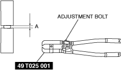
1.Adjust opening A of the SST to the standard by rotating the adjustment bolt.
ac8wzw00002095
|
-
Standard [VIN:Except 3M*]
-
Approx. 4.6 mm {0.18 in}
-
Standard [VIN: 3M*]
-
Approx. 4.5 mm {0.18 in}
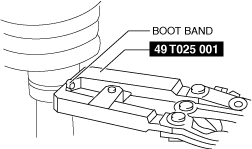
2.Crimp the boot band using the SST.
ac8wzw00002096
|
3.Verify that crimp B of the boot band is within the standard.
ac8wzw00002097
|
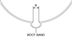
-
Standard [VIN:Except 3M*]
-
1.2—4.0 mm {0.05—0.15 in}
-
Standard [VIN: 3M*]
-
2.0—3.0 mm {0.08—0.11 in}
-
• If width B of the crimp exceeds the standard, reduce opening width A of the SST and crimp the boot band again.• If crimp B is less than the standard, increase opening A of the SST and crimp a new boot band.
4.Verify that the boot band does not protrude from the band assembly area.
-
• If the boot band protrudes from the assembly area, replace it with a new one and repeat Steps 1 to 3.
Boot (Transaxle Side) Assembly Note
-
Note
-
• The boot shapes on the wheel side and the transaxle side are different. Do not assemble the wrong boot by mistake.
1.Insert the shaft through the boot (transaxle side) with the vinyl tape left wrapped around the spline area of the shaft.
2.Remove the vinyl tape wrapped around the spline of the shaft.
Tripod Joint, Snap Ring Assembly Note
-
Caution
-
• Be careful not to scratch the roller area when using a hammer and urethane bar or equivalent. Otherwise, the part could be damaged.
-
Note
-
• If the tripod joint cannot be assembled to the shaft, lightly tap the tripod joint evenly using a hammer and urethane bar or equivalent, and assemble the tripod joint to the shaft.
1.Assemble the tripod joint with the shaft and tripod joint alignment marks aligned.
ac8wzw00002091
|
2.Assemble a new snap ring using snap ring pliers.
ac8wzw00002092
|
3.Verify that the snap ring is assembled correctly in the groove of the shaft.
Bearing Assembly Note
1.Install the new bearing using the SST and the press.
ac8wzw00002098
|
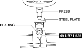
Dust Cover Assembly Note
1.Assemble a new dust cover using the SST and the press.
ac8wzw00002099
|
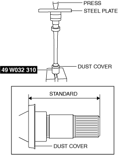
2.Verify that the installation position of the dust cover is within the standard.
-
Standard
-
88.1—89.3 mm {3.47—3.51 in}
Outer Ring, Clip Assembly Note
1.Apply the specified grease to the outer ring and boot (transaxle side).
-
Note
-
• Apply the grease from the tube. Do not touch the grease directly with your hand.
Boot (transaxle side) grease amount [Except Mexico]
|
Engine type |
Grease amount |
|
|---|---|---|
|
SKYACTIV-G 2.0 (MTX)
|
LH
|
140—160 g {4.94—5.64 oz}
|
|
SKYACTIV-G 2.0 (ATX)
|
LH
|
130—150 g {4.59—5.29 oz}
|
|
RH
|
130—150 g {4.59—5.29 oz}
|
|
|
SKYACTIV-G 2.5 (MTX)
|
LH
|
165—185 g {5.83—6.52 oz}
|
|
SKYACTIV-G 2.5 (ATX)
|
LH
|
135—155 g {4.77—5.46 oz}
|
|
RH
|
135—155 g {4.77—5.46 oz}
|
|
Boot (transaxle side) grease amount [Mexico]
|
Engine type |
Grease amount |
|
|---|---|---|
|
SKYACTIV-G 2.0
|
LH
|
110—130 g {3.89—4.58 oz}
|
|
RH
|
110—130 g {3.89—4.58 oz}
|
|
|
SKYACTIV-G 2.5 (MTX)
|
LH
|
116—136 g {4.10—4.79 oz}
|
|
RH
|
116—136 g {4.10—4.79 oz}
|
|
|
SKYACTIV-G 2.5 (ATX)
|
LH
|
110—130 g {3.89—4.58 oz}
|
|
RH
|
110—130 g {3.89—4.58 oz}
|
|
-
Caution
-
• Be careful that dust and dirt do not get on the inside of the outer ring.
2.Insert the outer ring to the shaft.
3.Assemble a new clip using a screwdriver. (With clip)
am3zzw00023111
|
4.Assemble the boot (transaxle side) to the outer ring.
5.Set the drive shaft to the standard length.
Drive shaft (tripod joint) full length (standard) [Except Mexico]
|
Engine type |
Full length (standard) |
|
|---|---|---|
|
SKYACTIV-G 2.0 (MTX)
|
LH
|
663.3—673.3 mm {26.12—26.50 in}
|
|
SKYACTIV-G 2.0 (ATX)
|
LH
|
653.7—663.7 mm {25.74—26.12 in}
|
|
RH
|
1034.7—1044.7 mm {40.737—41.129 in}
|
|
|
SKYACTIV-G 2.5 (MTX)
|
LH
|
662.2—672.2 mm {26.08—26.46 in}
|
|
SKYACTIV-G 2.5 (ATX)
|
LH
|
654.1—664.1 mm {25.76—26.14 in}
|
|
RH
|
1035.1—1045.1 mm {40.752—41.145 in}
|
|
Drive shaft (tripod joint) full length (standard) [Mexico]
|
Engine type |
Full length (standard) |
|
|---|---|---|
|
SKYACTIV-G 2.0 (MTX)
|
LH
|
658.3—668.3 mm {25.92—26.31 in}
|
|
RH
|
1021.0—1031.0 mm {40.197—40.590 in}
|
|
|
SKYACTIV-G 2.0 (ATX)
|
LH
|
645.3—655.3 mm {25.41—25.79 in}
|
|
RH
|
1030.5—1040.5 mm {40.571—40.964 in}
|
|
|
SKYACTIV-G 2.5 (MTX)
|
LH
|
656.2—666.2 mm {25.84—26.22 in}
|
|
RH
|
1021.2—1031.2 mm {40.205—40.598 in}
|
|
|
SKYACTIV-G 2.5 (ATX)
|
LH
|
645.3—655.3 mm {25.41—25.79 in}
|
|
RH
|
1027.0—1037.0 mm {40.434—40.826 in}
|
|
6.Release any trapped air from the boot by carefully lifting up the small end of the boot with a screwdriver wrapped in a clean cloth.
-
Note
-
• Do not damage the boot. Verify that there is no grease leakage.• If the boot is deformed, it may not be possible to perform the full-length adjustment of the shaft.
ac8wzw00002101
|
7.Verify that the drive shaft length is within the standard when the inside of the boot is at atmospheric pressure.
-
• If not within the standard, repeat from Step 5.
Boot Band (Transaxle Side) Assembly Note (VIN: JM*)
-
Warning
-
• Your hands could be injured while assembling the boot band. Therefore always wear gloves.
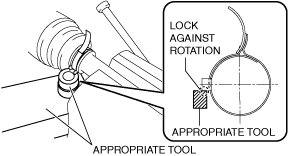
1.Apply rust prevention oil to the inside of the boot band.
2.Lock the boot band against rotation using an appropriate tool as shown in the figure.
am3uuw00011981
|
-
Caution
-
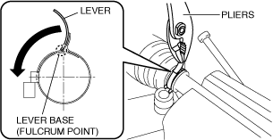
• Do not put the boot band back to its original position after bending it using pliers because it will damage the boot band.
3.Using a pair of pliers, grip the lever at the base (fulcrum point) and rotate it in the direction of the arrow.
am6xuw00011612
|
-
Caution
-
• If the lever springs back, press it back in no more than 3 times to prevent damage to the boot band.
4.Hold the bent lever using a hand and secure it temporarily by pinching the lock clip using pliers.
ac8wzw00002102
|
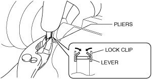
5.Lightly press the lock clip using a hammer so that the clearance of the lock clip is 1 mm {0.04 in} or less.
am3uuw00011984
|

-
• If there is any malfunction, replace with a new band.
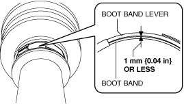
6.Verify that the clearance between the boot band and boot band lever is 1 mm {0.04 in} or less.
am3uuw00011985
|
-
• If there is any malfunction, replace with a new boot band.
7.After assembling the boot band, perform the following verification.
-
• The boot band does not protrude from the band assembly area.• The lever is not deformed.• The boot and boot band are not damaged.• The boot is not damaged.
Boot Band (Transaxle Side) Assembly Note (VIN: 3M*)]
Large diameter side
1.Grasp the boot band at the point shown in the figure using pliers and tighten the boot band.
am3zzw00013536
|

Small diameter side
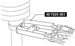
1.Adjust opening C of the SST to the standard by rotating the adjustment bolt.
azzzcw00000102
|

-
Standard
-
Approx. 4.5 mm {0.18 in}
2.Crimp the boot band using the SST.
am3uuw00009858
|
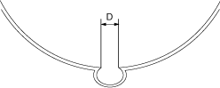
3.Verify that crimp D of the boot band is within the standard.
atstjw00000050
|
-
Standard
-
2.0—3.0 mm {0.08—0.11 in}
-
• If crimp D exceeds the standard, decrease opening C of the SST and crimp the boot band again.• If crimp D is less than the standard, increase opening C of the SST and crimp a new boot band.
4.Verify that the boot band does not protrude from the band assembly area.
-
• If the boot band protrudes from the assembly area, replace it with a new one and repeat Steps 1 to 3.