WHEEL HUB, STEERING KNUCKLE REMOVAL/INSTALLATION
WHEEL HUB, STEERING KNUCKLE REMOVAL/INSTALLATION
SM2335012
id031100800400
Replacement part
|
Locknut
Quantity: 1
Location of use: Front drive shaft
|
Front wheel hub bolt
Quantity: 5
Location of use: Front wheel hub
|
Snap pin
Quantity: 1
Location of use: Tie-rod end
|
|
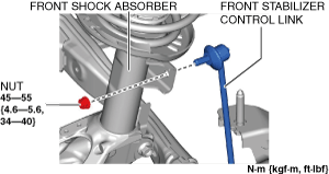
Front shock absorber installation nut
Quantity: 1
Location of use: Front shock absorber and steering knuckle component
|
Front shock absorber installation bolt
Quantity: 1
Location of use: Front shock absorber and steering knuckle component
|
Oil and chemical type
|
Grease
Type: L2Y1 33247 or equivalent
|
-
Caution
-
• If the front ABS wheel-speed sensor wiring harness is pulled by mistake when performing this procedure, it could cause an open circuit. Before servicing, disconnect the front ABS wheel-speed sensor and set it aside so that the wiring harness will not be pulled by mistake.
1.Remove the wheel and tire. (See WHEEL AND TIRE REMOVAL/INSTALLATION.)
2.Disconnect the rubber from the bracket.
am3zzw00023076
|
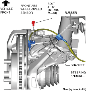
3.Disconnect the front ABS wheel-speed sensor wiring harness on the steering knuckle and set it aside so that it does not interfere with the servicing.
4.Remove the clip from the bracket.
am3zzw00023077
|
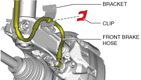
5.Remove the front brake hose from the bracket.
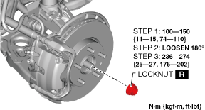
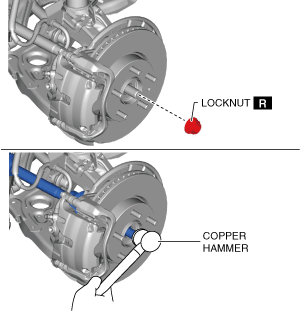
6.Remove the locknut with the brake pedal depressed. (See Locknut Installation Note.)
am3zzw00036208
|
-
Caution
-
• When removing the locknut, remove it manually without using an electric or pneumatic tool. Otherwise, the locknut may seize.• When removing the locknut, do not apply load at the ground to the axle. Otherwise, it could damage the wheel hub.
7.Temporarily install a spare nut to the front drive shaft.
8.Tap the nut with a copper hammer and separate the front drive shaft from the axle.
9.Remove the front brake caliper component and suspend it in a place out of the way using a cable. (See FRONT BRAKE DISC REMOVAL/INSTALLATION.)
10.Remove the front disc plate. (See FRONT BRAKE DISC REMOVAL/INSTALLATION.)
11.Remove the front stabilizer control link from the front shock absorber.
am3zzw00023083
|
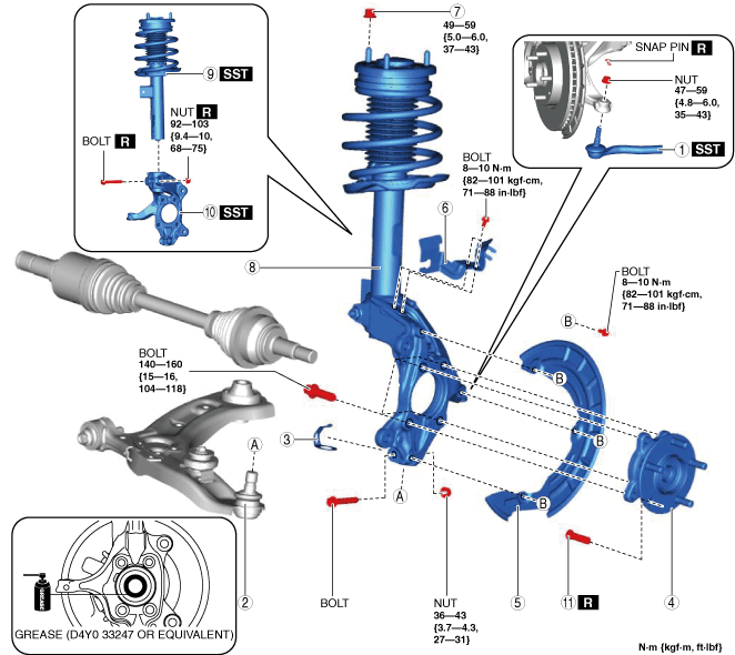
12.Remove in the order shown in the figure.
13.Install in the reverse order of removal.
14.When the steering knuckle is replaced, inspect the wheel alignment and adjust it if necessary. (See FRONT WHEEL ALIGNMENT [(US)].)
am3zzw00034653
|
|
1
|
Tie-rod end
(See TIE-ROD END REPLACEMENT.)
|
|
2
|
Front lower arm ball joint
|
|
3
|
Ball joint cover
|
|
4
|
Front wheel hub
|
|
5
|
Dust cover
|
|
6
|
Bracket
|
|
7
|
Front shock absorber upper nut
|
|
8
|
Front shock absorber and steering knuckle component
|
|
9
|
Front shock absorber and coil spring
|
|
10
|
Steering knuckle
|
|
11
|
Front wheel hub bolt
|
Front Wheel Hub Bolt Removal Note
-
Note
-
• Only remove a front wheel hub bolt if it is malfunctioning.
1.Remove the front wheel hub bolt from the front wheel hub using a press.
ac8wzw00002017
|
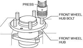
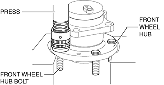
Front Wheel Hub Bolt Installation Note
1.Press fit the new front wheel hub bolt to the front wheel hub.
ac8wzw00002018
|
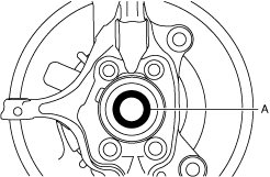
Front Wheel Hub Installation Note
1.Apply grease (L2Y1 33247 or equivalent) to the wheel bearing inner race and front drive shaft contact surfaces (area A in the figure).
am3zzw00034654
|
2.Install the front wheel hub, dust cover, and steering knuckle component.
Locknut Installation Note
-
Caution
-
• When installing the locknut, install it manually without using an electric or pneumatic tool. Otherwise, the locknut may seize and the tightening force of the wheel hub may decrease and cause excessive play or abnormal noise.• When installing the locknut, do not apply load at the ground to the axle. Otherwise, it could damage the wheel hub.
1.If dust or grease is on the drive shaft thread area, wipe it off with a cloth.
2.Working with two people, one should depress and hold the pedal down.
3.While the brake pedal is depressed, the other should tighten the locknut using the following procedure.
am3zzw00036209
|