DTC P2503:00 [PCM (SKYACTIV-G)]
DTC P2503:00 [PCM (SKYACTIV-G)]
SM2334553
id0102t4709600
-
Note
-
• To determine the malfunctioning part, proceed with the diagnostics from “Function Inspection Using M-MDS”.
Details On DTCs
|
Description |
Generator system: Voltage generated by generator is low |
||
|---|---|---|---|
|
Detection condition
|
Determination conditions
|
• A condition continues for a specified period of time in which the target generator output current calculated by the PCM is 20 A or more and the generator output voltage is 8.5 V or less.
|
|
|
Preconditions
|
• While engine is running
|
||
|
Malfunction determination period
|
• 5 s period
|
||
|
Drive cycle
|
• 1
|
||
|
Self test type
|
• CMDTC self test
|
||
|
Sensor used
|
• PCM
• Generator
|
||
|
Fail-safe function
|
• Generator control is inhibited.
|
||
|
Vehicle status when DTCs are output
|
• The following vehicle conditions differ depending on the type of malfunction:
|
||
|
Possible cause
|
• Poor connection of the following parts:
• Connector or terminal malfunction of the following parts:
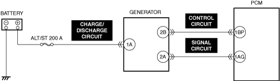
• Short to ground or open circuit in generator charge/discharge circuit
• Short to ground in any of the following generator circuits.
• Open circuit in any of the following generator circuits.
• Drive belt exceeds limit
• Generator malfunction
• Battery malfunction
• PCM malfunction
|
||
 |
|||
 |
|||
 |
|||
Function Explanation (DTC Detection Outline)
• When the charge/discharge circuit for the power supplying the vehicle is normal, the vehicle will operate normally.
• Although a power generation command is made to the generator, a malfunction is diagnosed indicating no output from the generator, and verification of vehicle malfunctions/safety assurance is performed.
Repeatability Verification Procedure
1. Clear the DTC from the PCM memory using the M-MDS. (See CLEARING DTC.)
2. Start the engine.
3. Leave for 30 s while idling with high electrical load.
PID Item/Simulation Item Used In Diagnosis
• Not applicable
Function Inspection Using M-MDS
|
Step |
Inspection |
Results |
Action |
|---|---|---|---|
|
1
|
PURPOSE: RECORD VEHICLE STATUS WHEN DTC WAS DETECTED TO UTILIZE WITH REPEATABILITY VERIFICATION
• Record the freeze frame data/snapshot data.
|
—
|
Go to Troubleshooting Diagnostic Procedure to perform the procedure from Step 1.
|
Troubleshooting Diagnostic Procedure
Intention of troubleshooting procedure
• Step 1—8
-
― Perform an inspection of each signal transmission system.
• Step 9
-
― Perform a generator drive belt related inspection.
• Step 10
-
― Perform a unit inspection of the generator.
• Step 11
-
― Perform a unit inspection of the battery.
• Repair completion verification
-
― Verify that the primary malfunction is resolved and there are no other malfunctions.
|
Step |
Inspection |
Results |
Action |
|---|---|---|---|
|
1
|
PURPOSE: VERIFY RELATED REPAIR INFORMATION OR SERVICE INFORMATION AVAILABILITY
• Verify related Service Bulletins, on-line repair information, or Service Information availability.
• Is any related Information available?
|
Yes
|
Perform repair or diagnosis according to the available information.
• If the vehicle is not repaired, go to the next step.
|
|
No
|
Go to the next step.
|
||
|
2
|
PURPOSE: VERIFY IF POOR CONNECTION OF EACH PART AFFECTS DIAGNOSTIC RESULTS
• Switch the ignition off.
• Inspect the connection condition (part installation condition, connector connection condition) for the following parts:
• Is the connection condition (part installation condition, connector connection condition) for each part normal?
|
Yes
|
Go to the next step.
|
|
No
|
Connect each part or the connector correctly, then go to Step 11.
|
||
|
3
|
PURPOSE: INSPECT BATTERY CONNECTOR FOR MALFUNCTION
• Inspect the applicable connector and terminal. (See CONNECTOR INSPECTION.)
• Are the connector and terminal normal?
|
Yes
|
Go to the next step.
|
|
No
|
Repair or replace the malfunctioning location, then go to Step 11.
|
||
|
4
|
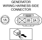
PURPOSE: INSPECT GENERATOR CONNECTOR FOR MALFUNCTION
• Inspect the applicable connector and terminal. (See CONNECTOR INSPECTION.)
• Are the connector and terminal normal?
|
Yes
|
Go to the next step.
|
|
No
|
Repair or replace the malfunctioning location, then go to Step 11.
|
||
|
5
|
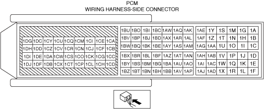
PURPOSE: INSPECT PCM CONNECTOR FOR MALFUNCTION
• Inspect the applicable connector and terminal. (See CONNECTOR INSPECTION.)
• Are the connector and terminal normal?
|
Yes
|
Go to the next step.
|
|
No
|
Repair or replace the malfunctioning location, then go to Step 11.
|
||
|
6
|
PURPOSE: INSPECT GENERATOR CHARGE/DISCHARGE CIRCUIT FOR SHORT TO GROUND AND OPEN CIRCUIT
• Inspect the power supply circuit for an open circuit and short to ground. (See CIRCUIT INSPECTION.)
• Is the circuit normal?
|
Yes
|
Go to the next step.
|
|
No
|
Repair or replace the malfunctioning location, then go to Step 11.
|
||
|
7
|
PURPOSE: INSPECT GENERATOR CONTROL CIRCUIT AND SIGNAL CIRCUIT FOR SHORT TO GROUND
• Inspect the applicable circuit for a short to ground. (See CIRCUIT INSPECTION.)
• Is the circuit normal?
|
Yes
|
Go to the next step.
|
|
No
|
Repair or replace the malfunctioning location, then go to Step 11.
|
||
|
8
|
PURPOSE: INSPECT GENERATOR CONTROL CIRCUIT AND SIGNAL CIRCUIT FOR OPEN CIRCUIT
• Inspect the applicable circuit for open circuit. (See CIRCUIT INSPECTION.)
• Is the circuit normal?
|
Yes
|
Go to the next step.
|
|
No
|
Repair or replace the malfunctioning location, then go to Step 11.
|
||
|
9
|
PURPOSE: VERIFY IF MALFUNCTION RELATED TO GENERATOR DRIVE BELT AFFECTS DIAGNOSTIC RESULTS
• Inspect the generator drive belt. (See DRIVE BELT INSPECTION [SKYACTIV-G (WITH CYLINDER DEACTIVATION (US))].) (See DRIVE BELT INSPECTION [SKYACTIV-G (WITHOUT CYLINDER DEACTIVATION (US))].)
• Is the indicator mark on the drive belt auto tensioner within the normal range?
|
Yes
|
Go to the next step.
|
|
No
|
Replace the generator drive belt, then go to the next step.
|
||
|
10
|
PURPOSE: INSPECT GENERATOR FOR MALFUNCTION
• Inspect the applicable part. (See GENERATOR INSPECTION [SKYACTIV-G (WITH CYLINDER DEACTIVATION (US))].) (See GENERATOR INSPECTION [SKYACTIV-G (WITHOUT CYLINDER DEACTIVATION (US))].)
• Is the part normal?
|
Yes
|
Go to the next step.
|
|
No
|
Repair or replace the malfunctioning location, then go to the next step.
|
||
|
11
|
PURPOSE: VERIFY CONDITIONS OF BATTERY
• Inspect the battery. (See BATTERY INSPECTION [(US)].)
|
—
|
Follow the inspection instructions.
Go to repair completion verification.
|
|
Repair completion verification 1
|
PURPOSE: VERIFY THAT VEHICLE IS REPAIRED
• Install/connect the part removed/disconnected during the troubleshooting procedure.
• Clear the DTC recorded in the memory. (See CLEARING DTC.)
• Replicate the vehicle conditions at the time the DTC was detected using the following procedure.
• Perform the DTC inspection for the PCM. (See DTC INSPECTION.)
• Is the same Pending DTC present?
|
Yes
|
Refer to the controller area network (CAN) malfunction diagnosis flow to inspect for a CAN communication error.
If the CAN communication is normal, perform the diagnosis from Step 1.
• If the malfunction recurs, replace the PCM, then go to the next step. (See PCM REMOVAL/INSTALLATION [SKYACTIV-G (WITH CYLINDER DEACTIVATION (US))].) (See PCM REMOVAL/INSTALLATION [SKYACTIV-G (WITHOUT CYLINDER DEACTIVATION (US))].)
|
|
No
|
Go to the next step.
|
||
|
Repair completion verification 2
|
PURPOSE: VERIFY IF OTHER DTCs DISPLAYED
• Perform the DTC inspection. (See DTC INSPECTION.)
• Are any other DTCs displayed?
|
Yes
|
Repair the malfunctioning location according to the applicable DTC troubleshooting.
|
|
No
|
DTC troubleshooting completed.
|