DTC P3498:00 OR P349B:00 [PCM (SKYACTIV-G)]
DTC P3498:00 OR P349B:00 [PCM (SKYACTIV-G)]
SM2334489
id0102t4500400
-
Note
-
• To determine the malfunctioning part, proceed with the diagnostics from “Function Inspection Using M-MDS”.
Details On DTCs
|
Description |
Cylinder deactivation control system: • P3498:00: No.1 cylinder valve is stuck closed
• P349B:00: No.4 cylinder valve is stuck closed
|
|
|---|---|---|
|
Detection condition
|
Determination conditions
|
• The crankshaft fluctuation rate exceeds the specified value for every 200 rotations of the crankshaft after recovery from cylinder deactivation control.
|
|
Preconditions
|
• Battery voltage: 9—18 V *1
• Engine speed: 500—6,500 rpm *1
• Engine coolant temperature: 20 °C {68 °F} or more *1
• Fuel-cut control not implemented
• Crankshaft installation tolerance learning completed
• Engine condition is stabilized (not directly after gear change)
*1: Standard can be verified by displaying PIDs using M-MDS
|
|
|
Malfunction determination period
|
• 200 rotations of crankshaft (misfire which may damage catalytic converter)
|
|
|
Drive cycle
|
• 1
|
|
|
Self test type
|
• CMDTC self test
|
|
|
Sensor used
|
• CKP sensor
• MAF sensor
• MAP sensor
|
|
|
Fail-safe function
|
• Limits intake air amount
• Implement fuel-cut control (If cylinder is filled with fuel when valve is stuck closed, fuel-cut on No.1 or No.4 cylinder is performed because engine could be damaged at compression stroke).
|
|
|
Vehicle status when DTCs are output
|
• Possibility of engine damage occurring.
• Rough idling, poor acceleration, stalling
|
|
|
Possible cause
|
• Improper operation of ignition system
• Fuel injector malfunction
• OCV for No.1 cylinder deactivation malfunction
• OCV for No.4 cylinder deactivation malfunction
• Switchable HLA malfunction
• Engine oil solenoid valve malfunction
• Erratic signal to PCM
• Air leakage from intake air system (between intake manifold and cylinder head)
• Poor drive belt assembly or adhesion of oil
• Decoupling ring tensioner malfunction (With Mazda M Hybrid)
• Drive belt auto tensioner malfunction (Without Mazda M Hybrid)
• Engine malfunction
• PCM malfunction
|
|
System Wiring Diagram
• Not applicable.
Function Explanation (DTC Detection Outline)
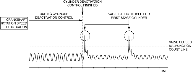
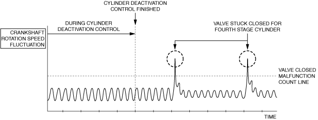
• The PCM detects the crankshaft rotation speed based on the crankshaft position sensor signal. While the engine is running, the crankshaft rotation speed varies slightly by the effect of combustion at each cylinder, however, the rotation speed changes rapidly if a valve is stuck closed after recovery from cylinder deactivation control. (If valve is stuck closed, engine oil and fuel accumulates in cylinder, and by its ignition there, there is possibility of engine damage) The PCM calculates the frequency of changes (fluctuation rate) in rapid rotation speed for every specified number of crankshaft rotations. When the crankshaft fluctuation rate exceeds a certain value after recovery from cylinder deactivation, the PCM determines that No.1 or 4 cylinder valve is stuck and stores a DTC.
P3498:00
am3zzw00033566
|
P349B:00
am3zzw00033567
|
Repeatability Verification Procedure
• Not applicable
PID Item/Simulation Item Used In Diagnosis
PID/DATA monitor item table
|
PIDs |
Reference |
|---|---|
|
APP1
|
|
|
APP2
|
|
|
ECT
|
|
|
ECT_VOLT
|
|
|
IAT
|
|
|
MAF
|
|
|
MAP
|
|
|
MAP_VOLT
|
|
|
ENG_RPM
|
|
|
TP_RELAT
|
|
|
VSS
|
Function Inspection Using M-MDS
|
STEP |
INSPECTION |
RESULTS |
ACTION |
|---|---|---|---|
|
1
|
PURPOSE: VERIFY RELATED REPAIR INFORMATION OR SERVICE INFORMATION AVAILABILITY
• Verify related Service Bulletins, on-line repair information, or Service Information availability.
• Is any related Information available?
|
Yes
|
Perform repair or diagnosis according to the available information.
• If the vehicle is not repaired, go to the next step.
|
|
No
|
Go to the next step.
|
||
|
2
|
PURPOSE: IDENTIFY TRIGGER DTC FOR FREEZE FRAME DATA
• Is the DTC P3498:00 or P349B:00 on freeze frame data?
|
Yes
|
Go to the next step.
|
|
No
|
Go to the troubleshooting procedure for DTC on freeze frame data.
|
||
|
3
|
PURPOSE: RECORD VEHICLE STATUS WHEN DTC WAS DETECTED TO UTILIZE WITH REPEATABILITY VERIFICATION
• Record the freeze frame data/snapshot data.
|
—
|
Go to the next step.
|
|
4
|
PURPOSE: INSPECT FOR OTHER RELATED DTCs
• Perform the DTC inspection for the PCM. (See DTC INSPECTION.)
• Are any other DTCs displayed?
|
Yes
|
Repair the malfunctioning location according to the applicable DTC troubleshooting.
|
|
No
|
Go to the next step.
|
||
|
5
|
PURPOSE: VERIFY IF THERE IS PID ITEM CAUSING DRASTIC CHANGES OF ACCELERATION FLUCTUATION BY INPUT SIGNAL TO PCM
• Start the engine.
• Access the following PIDs using the M-MDS: (See PID/DATA MONITOR INSPECTION.)
• Is there a PID item affected by acceleration fluctuation?
|
Yes
|
Inspect the suspected sensor and related wiring harness.
• If there is any malfunction:
• If there is no malfunction:
|
|
No
|
Go to the next step.
|
Troubleshooting Diagnostic Procedure
Intention of troubleshooting procedure
• Step 1—2
-
― Perform an ignition system parts inspection.
• Step 3—6
-
― Perform an engine oil related inspection.
• Step 7
-
― Perform a fuel injector control system inspection.
• Step 8—14
-
― Perform an inspection of parts which may be affected by misfire except for ignition-related parts and fuel injection control-related parts.
• Repair completion verification
-
― Verify that primary malfunction is resolved and there are no other malfunctions.
|
STEP |
INSPECTION |
RESULTS |
ACTION |
|---|---|---|---|
|
1
|
PURPOSE: INSPECT SPARK PLUG FOR MALFUNCTION
• Inspect the applicable part. (See SPARK PLUG INSPECTION [SKYACTIV-G (WITH CYLINDER DEACTIVATION (US))].)
• Is the part normal?
|
Yes
|
Go to the next step.
|
|
No
|
Repair or replace the malfunctioning location and perform the repair completion verification.
|
||
|
2
|
PURPOSE: INSPECT IGNITION COIL FOR MALFUNCTION
• Inspect the applicable part. (See IGNITION COIL INSPECTION [SKYACTIV-G (WITH CYLINDER DEACTIVATION (US))].)
• Is the part normal?
|
Yes
|
Go to the next step.
|
|
No
|
Repair or replace the malfunctioning location and perform the repair completion verification.
|
||
|
3
|
PURPOSE: INSPECT OCV FOR No.1 CYLINDER DEACTIVATION FOR MALFUNCTION
• Inspect the applicable part. (See OIL CONTROL VALVE (OCV) FOR CYLINDER DEACTIVATION INSPECTION [SKYACTIV-G (WITH CYLINDER DEACTIVATION (US))].)
• Is the part normal?
|
Yes
|
Go to the next step.
|
|
No
|
Repair or replace the malfunctioning location and perform the repair completion verification.
|
||
|
4
|
PURPOSE: INSPECT OCV FOR No.4 CYLINDER DEACTIVATION FOR MALFUNCTION
• Inspect the applicable part. (See OIL CONTROL VALVE (OCV) FOR CYLINDER DEACTIVATION INSPECTION [SKYACTIV-G (WITH CYLINDER DEACTIVATION (US))].)
• Is the part normal?
|
Yes
|
Go to the next step.
|
|
No
|
Repair or replace the malfunctioning location and perform the repair completion verification.
|
||
|
5
|
PURPOSE: INSPECT SWITCHABLE HLA FOR MALFUNCTION
• Inspect the applicable part. (See HYDRAULIC LASH ADJUSTER (HLA) INSPECTION [SKYACTIV-G (WITH CYLINDER DEACTIVATION (US))].)
• Is the part normal?
|
Yes
|
Go to the next step.
|
|
No
|
Repair or replace the malfunctioning location and perform the repair completion verification.
|
||
|
6
|
PURPOSE: INSPECT ENGINE OIL SOLENOID VALVE FOR MALFUNCTION
• Inspect the applicable part. (See ENGINE OIL SOLENOID VALVE INSPECTION [SKYACTIV-G (WITH CYLINDER DEACTIVATION (US))].)
• Is the part normal?
|
Yes
|
Go to the next step.
|
|
No
|
Repair or replace the malfunctioning location and perform the repair completion verification.
|
||
|
7
|
PURPOSE: INSPECT FUEL INJECTOR FOR MALFUNCTION
• Inspect the applicable part. (See FUEL INJECTOR INSPECTION [SKYACTIV-G (WITH CYLINDER DEACTIVATION (US))].)
• Is the part normal?
|
Yes
|
Go to the next step.
|
|
No
|
Repair or replace the malfunctioning location and perform the repair completion verification.
|
||
|
8
|
PURPOSE: VERIFY IF MALFUNCTION RELATED TO INTAKE-AIR SYSTEM IS CAUSE OF VALVE BEING STUCK CLOSED
• Visually inspect for loose, cracked or damaged hoses on intake air system.
• Is there any malfunction?
|
Yes
|
Repair or replace the malfunctioning location and perform the repair completion verification.
|
|
No
|
Go to the next step.
|
||
|
9
|
PURPOSE: VERIFY IF POOR DRIVE BELT ASSEMBLY IS CAUSE OF VALVE BEING STUCK CLOSED
• Verify the condition of the drive belt assembly. (See DRIVE BELT INSPECTION [SKYACTIV-G (WITH CYLINDER DEACTIVATION (US))].)
• Is there any malfunction?
|
Yes
|
Assemble drive belt correctly and perform the repair completion verification.
|
|
No
|
Go to the next step.
|
||
|
10
|
PURPOSE: VERIFY IF FOREIGN MATTER ON DRIVE BELT IS CAUSE OF VALVE BEING STUCK CLOSED
• Verify if oil is on the drive belt.
• Is there foreign matter on the drive belt?
|
Yes
|
Remove the foreign matter on the drive belt and perform the repair completion verification.
|
|
No
|
Vehicles with Mazda M Hybrid:
• Go to the next step.
Vehicles without Mazda M Hybrid:
• Go to Step 12.
|
||
|
11
|
PURPOSE: INSPECT DECOUPLING RING TENSIONER FOR MALFUNCTION
• Inspect the applicable part.
• Is the part normal?
|
Yes
|
Go to the next step.
|
|
No
|
Repair or replace the malfunctioning location and perform the repair completion verification.
|
||
|
12
|
PURPOSE: INSPECT DRIVE BELT AUTO TENSIONER FOR MALFUNCTION
• Inspect the applicable part. (See DRIVE BELT AUTO TENSIONER INSPECTION [SKYACTIV-G (WITH CYLINDER DEACTIVATION (US))].)
• Is the part normal?
|
Yes
|
Go to the next step.
|
|
No
|
Repair or replace the malfunctioning location and perform the repair completion verification.
|
||
|
13
|
PURPOSE: VERIFY IF MALFUNCTION RELATED TO ENGINE COMPRESSION IS CAUSE OF VALVE BEING STUCK CLOSED
• Inspect the engine compression. (See COMPRESSION INSPECTION [SKYACTIV-G (WITH CYLINDER DEACTIVATION (US))].)
• Are compression pressures within specification?
|
Yes
|
Go to the next step.
|
|
No
|
Replace or overhaul the engine and perform the repair completion verification.
|
||
|
14
|
PURPOSE: VERIFY IF MALFUNCTION RELATED TO SEALING OF ENGINE UNIT (COMBUSTION CHAMBER AND ENGINE COOLANT PASSAGE) IS CAUSE OF MISFIRE
• Perform the “ENGINE COOLANT LEAKAGE INSPECTION”. (See ENGINE COOLANT LEAKAGE INSPECTION [SKYACTIV-G (WITH CYLINDER DEACTIVATION (US))].)
• Does the radiator cap tester needle drop even though there is no engine coolant leakage from the radiator or the hoses?
|
Yes
|
Engine coolant leakage from the engine (between the combustion chamber and the engine coolant passage) may have occurred.
• Verify the conditions of the gasket and the cylinder head.
|
|
No
|
Go to the next step.
|
||
|
15
|
PURPOSE: INSPECT FOR MALFUNCTION DUE TO INTERNAL ENGINE WEAR, DAMAGE
• Inspect for the following engine internal parts:
• Are all items normal?
|
Yes
|
Engine internal parts are normal.
• Go to the next step.
|
|
No
|
Repair or replace the malfunctioning location and perform the repair completion verification.
|
||
|
Repair completion verification 1
|
PURPOSE: VERIFY THAT VEHICLE IS REPAIRED
• Install/connect the part removed/disconnected during the troubleshooting procedure.
• Clear the DTC recorded in the memory. (See CLEARING DTC.)
• Replicate the vehicle conditions at the time the DTC was detected using the following procedure.
• Perform the DTC inspection for the PCM. (See DTC INSPECTION.)
• Is the same Pending DTC present?
|
Yes
|
Refer to the controller area network (CAN) malfunction diagnosis flow to inspect for a CAN communication error.
If the CAN communication is normal, perform the diagnosis from Step 1.
• If the malfunction recurs, replace the PCM, then go to the next step. (See PCM REMOVAL/INSTALLATION [SKYACTIV-G (WITH CYLINDER DEACTIVATION (US))].)
|
|
No
|
Go to the next step.
|
||
|
Repair completion verification 2
|
PURPOSE: VERIFY IF OTHER DTCs DISPLAYED
• Perform the DTC inspection. (See DTC INSPECTION.)
• Are any other DTCs displayed?
|
Yes
|
Repair the malfunctioning location according to the applicable DTC troubleshooting.
|
|
No
|
DTC troubleshooting completed.
|