SERVICE CAUTIONS [(US)]
SERVICE CAUTIONS [(US)]
SM2334343
id0000000002x1
Injury/damage Prevention Precautions
Protection of the Vehicle
am6zzw00008910
|
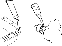
Preparation of Tools and Measuring Equipment
am6zzw00008911
|

Special Service Tools
am6zzw00008912
|
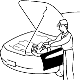
Malfunction Diagnosis System
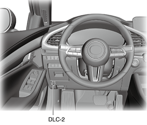
Connection to malfunction diagnosis system
-
• With the ignition switched off, connect the malfunction diagnosis system to the DLC-2 connector shown in the figure.
 am3zzw00026069
Oil Leakage Inspection
Using UV light (black light)
1.Remove any oil on the engine or transmission/transaxle.
-
Note
-
• Referring to the fluorescent dye instruction manual, mix the specified amount of dye into the engine oil or transmission/transaxle oil.
2.Pour the fluorescent dye into the engine oil or transmission/transaxle oil.
3.Allow the engine to run for 30 min.
4.Inspect for dye leakage by irradiating with UV light (black light), and identify the type of oil that is leaking.
5.If no dye leakage is found, allow the engine to run for another 30 min. or drive the vehicle then reinspect.
6.Find where the oil is leaking from, then make necessary repairs.
-
Note
-
• To determine whether it is necessary to replace the oil after adding the fluorescent dye, refer to the fluorescent dye instruction manual.
Not using UV light (black light)
1.Gather sample of the leaking oil using an absorbent white tissue.
am6zzw00008913
|
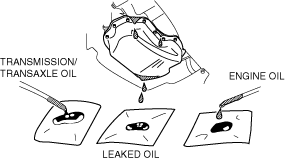
2.Then, gather some samples of engine and transmission/transaxle oil onto a white cloth or piece of paper.
-
• MT vehicles: transmission/transaxle oil• AT vehicles: ATF• CVT vehicles: continuously variable transaxle fluid
3.Compare the appearance and smell, and identify the type of oil that is leaking.
4.Remove any oil on the engine or transmission/transaxle.
5.Allow the engine to run for 30 min.
6.Check the area where the oil is leaking, then make necessary repairs.
Negative Battery Terminal Disconnection/Connection
-
Warning
-
• Before removing the SRS air bag system-related parts, always disconnect the negative battery terminal and wait for 1 min. or more to allow the back-up power supply to deplete its stored power. (See AIR BAG SYSTEM SERVICE WARNINGS [STANDARD DEPLOYMENT CONTROL SYSTEM – MEXICO SPEC.].) (See AIR BAG SYSTEM SERVICE WARNINGS [TWO-STEP DEPLOYMENT CONTROL SYSTEM – US/CANADA SPEC.].)
Switch the Power Supply Using the Push Button Start and Start the Engine
ac5uun00003215
|
Removal of Parts
am6zzw00008916
|

Control module configuration (initialization setting)
-
Caution
-
• If the configuration procedure is not completed correctly after replacing a control module in which configuration is required, the system will not operate normally. Therefore, perform the work in accordance with the replacement procedure in the workshop manual.
-
― Automatic configuration
-
• The main control module (built into instrument cluster) performs configuration of the new control module itself and automatically using the vehicle specification data sent via CAN lines.
― Configuration based on vehicle information read/write data-
• Reads the vehicle information from the control module prior to replacement, and writes the vehicle information to a new control module.
― Configuration by As-Built data:-
• Obtains the vehicle specification data when the vehicle is shipped from the factory, and writes the data to a new control module.• The configuration using As-Built data is used if the vehicle information cannot be read due to a damaged control module which is to be replaced, or if a DTC such as a configuration malfunction is detected.• If a control module having personalization features is configured using As-Built data, the settings personalized by the customer are initialized (to factory settings). In this case, verify the setting values made by the customer and change the personalized setting values using the “Programmable Parameters” from the M-MDS menu.
-
Disassembly
am6zzw00008917
|
Inspection During Removal, Disassembly
am6zzw00008918
|

Arrangement of Parts
am6zzw00008919
|

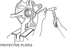
Cleaning of Parts
am6zzw00008920
|
-
Warning
-
• Using compressed air can cause dirt and other particles to fly out causing injury to the eyes. Wear protective eye wear whenever using compressed air.
Reassembly
|
Cotter pins
|
Gaskets
|
Locknuts (Nylon nuts)
|
Lock washers
|
|
Oil seals
|
O-rings
|
Spring pins
|
—
|
am6zzw00008921
|
-
― Sealant and gaskets, or both, should be applied to specified locations. When sealant is applied, parts should be installed before sealant hardens to prevent leakage.― Oil should be applied to the moving components of parts.― Specified oil or grease should be applied at the prescribed locations (such as oil seals) before reassembly.am6zzw00008922
Adjustment
am6zzw00008923
|
Rubber Parts and Tubing
am6zzw00008924
|

Hose Clamps
am6zzw00008925
|

-
Note
-
• Follow the description in each section because the clamps which are used with the fuel-related system differ from the one indicated above.
Torque Formulas
am6zzw00008926
|
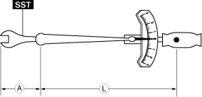
|
Torque Unit |
Formula |
|---|---|
|
N·m
|
N·m × [L/(L+A)]
|
|
kgf·m
|
kgf·m × [L/(L+A)]
|
|
kgf·cm
|
kgf·cm × [L/(L+A)]
|
|
ft·lbf
|
ft·lbf × [L/(L+A)]
|
|
in·lbf
|
in·lbf × [L/(L+A)]
|
Vise
am6zzw00008927
|
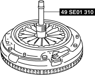
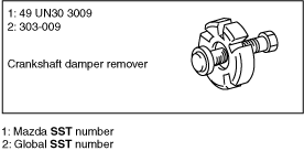
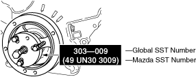
SST
Example (SST List)
am5ezw00006750
|
Example (In text)
am6zzw00005599
|
Emergency Engine Stop Operation
1.Continuously pressing the push button start or quickly pressing it any number of times while the engine is running or the vehicle is being driven will turn the engine off immediately. The ignition switches to ACC.
Cautions on Chassis Dynamometer Use
-
Note
-
• If the engine cannot be stopped using the push button start, perform an emergency engine stop operation. (See Cautions for vehicles with Mazda Radar Cruise Control (MRCC) system/Mazda Radar Cruise Control with stop & go function (MRCC with stop & go function) system/Traffic Jam Assist (TJA)/Smart Brake Support (SBS) system/Smart Brake Support [Rear] (SBS-R) system/Smart Brake Support [Rear Crossing] (SBS-RC) system/Distance & Speed Alert (DSA)/Lane-keep assist system.)
-
― Place a fan, preferably a vehicle-speed proportional type, in front of the vehicle.― Make sure the vehicle is in a facility with an exhaust gas ventilation system.― Keep the rear bumper cool by placing a cooling fan near the exhaust pipe so that the rear bumper does not get deformed by the heat from the exhaust.― Keep the area around the vehicle uncluttered so that heat does not build up.― Watch the water temperature gauge and do not overheat the engine.― Avoid added load to the engine and maintain normal driving conditions as much as possible.
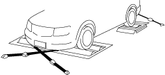
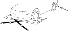
AWD inspection/service
Speedometer tester measurement
-
Caution
-
• Install the tension bar (chain wire) to the tie down hook and secure the vehicle to prevent it from rolling and running off.• Do not accelerate suddenly from a standstill or accelerate/decelerate rapidly.
-
Free roller type
-
1. Align the free rollers with the wheel base and tread, then set them on the floor properly.2. Drive the vehicle slowly onto the tester roller and free rollers.acxuuw000003273. Start the engine and accelerate gradually to inspect the speedometer.4. After inspection, decelerate gradually with gentle braking.
-
Propeller shaft removal type
-
1. Remove the propeller shaft. (See PROPELLER SHAFT REMOVAL/INSTALLATION [(US)].)2. Place the front wheels on the tester roller.acxuuw000003293. Accelerate gradually and inspect the speedometer.4. After inspection, decelerate gradually with gentle braking.5. Install the propeller shaft. (See PROPELLER SHAFT REMOVAL/INSTALLATION [(US)].)
Brake tester measurement
1.Place the wheels (front or rear) to be measured on the tester roller.
acxuuw00000328
|
2.Shift to the N position/neutral.
3.Activate the tester roller and measure braking force. If there is a large amount of brake drag force, the electronic control system coupling may be affected. Jack up all four wheels to eliminate the effect of the coupling and rotate each wheel by hand to verify the rotation condition.
Wheel balancer (on the vehicle balancer)
1.Jack up all four wheels.
2.Support the wheels (front or rear) on the side to be measured (near the wheels) using a wheel balancer sensor stand.
3.Support the wheels on the side not to be measured (near the wheels) using safety stands.
acxuuw00000330
|

4.Set up the wheel balancer and rotate the wheels using engine drive to measure the wheel balance.
Servicing on Vehicles with Electric Parking Brake
1.For vehicles with the electric parking brake, when the electric parking brake control module detects for 3 s or more that all of the following conditions are met during braking force inspection using a brake tester, the mode is automatically switched to “electric parking brake inspection mode”.
-
• Ignition is switched ON (engine on)• Shift lever is in neutral (MTX)• Selector lever is in N position (ATX)• Accelerator and brake pedals are not depressed• Front wheel speed is 0 km/h {0 mph}• Rear wheel speed is 3—12 km/h {2.0—7.4 mph}
-
Note
-
• When the mode is switched to the electric parking brake inspection mode, the electric parking brake warning light turns on.• The mode may not switch to the electric parking brake inspection mode depending on the specification of the brake tester being used. In this case, depress the parking brake using the normal electric parking brake switch operation and perform the braking force inspection.
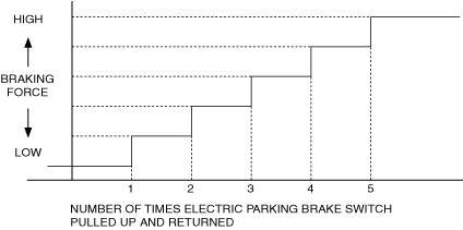
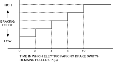
2.When the mode is switched to the electric parking brake inspection mode, the electric parking brake control module increases the braking force of the electric parking brake according to the electric parking brake switch operation as follows.
-
Electric parking brake switch is pulled up and returned for short periods (less than approx. 2 s)
-
• Increase the braking force by one step each time the operation is performed.ac5wzw00008436
-
Electric parking brake switch is held pulled up for 2 s or more
-
• Increase the braking force by one step each time 2 s have elapsed.ac5wzw00008437
3.When any of the following conditions is detected, stop the electric parking brake inspection mode.
-
• Shift lever is in position other than neutral (MTX)• Selector lever is in position other than N (ATX)• Accelerator pedal is depressed• Brake pedal is depressed• Front wheel speed is 1 km/h {0.7 mph} or more• Rear wheel speed is less than 3 km/h {1 mph}• Rear wheel speed is 12 km/h {7.5 mph} or more
-
Note
-
• When electric parking brake inspection mode is stopped, the electric parking brake warning light turns off.
Servicing on Vehicles with ABS/DSC
-
Note
-
• If the engine cannot be stopped using the push button start, perform an emergency engine stop operation. (See Emergency Engine Stop Operation.)
Cautions for vehicles with Mazda Radar Cruise Control (MRCC) system/Mazda Radar Cruise Control with stop & go function (MRCC with stop & go function) system/Traffic Jam Assist (TJA)/Smart Brake Support (SBS) system/Smart Brake Support [Rear] (SBS-R) system/Smart Brake Support [Rear Crossing] (SBS-RC) system/Distance & Speed Alert (DSA)/Lane-keep assist system
-
Caution
-
• If a vehicle with the following systems is inspected using a chassis dynamometer, always turn off each system before performing the inspection.
-
― Mazda Radar Cruise Control (MRCC) system― Mazda Radar Cruise Control with stop & go function (MRCC with stop & go function) system― Traffic Jam Assist (TJA)― Smart Brake Support (SBS) system― Smart Brake Support [Rear] (SBS-R) system― Smart Brake Support [Rear Crossing] (SBS-RC) system― Distance & Speed Alert (DSA)― Lane-keep assist system
• If a chassis dynamometer is used without turning off each system, automatic braking will operate and the inspection cannot be performed correctly.• In the event that a chassis dynamometer is used without turning off each system, take appropriate measures referring to the following as each of the system’s warning indication/warning light may be indicated and DTCs stored in the memory. -
-
― i-ACTIVSENSE warning indication/warning light is indicated― Master warning indication
-
1. If the warning indication/warning light is indicated, remove the vehicle from the chassis dynamometer and switch the ignition off.2. Switch the ignition back ON and drive the vehicle at 10 km/h {6.2 mph} or more to verify that the warning light turns off.3. Because DTCs are stored, clear DTCs according to the memory clearing procedure.
-
― Master warning indication― Displays “Safety and Driver Support Systems Temporarily Disabled.”, “Front Radar Obscured. Drive Safely.”
-
1. If a warning indication and a message is displayed, remove the vehicle from the chassis dynamometer and switch the ignition off.2. Switch the ignition back ON and verify that the warning light is turned off and the message is cleared.3. Because DTCs are stored, clear the DTCs according to the memory clearing procedure.