WARNING/INDICATION/ALARM [SKYACTIV-G (WITHOUT CYLINDER DEACTIVATION (US))]
WARNING/INDICATION/ALARM [SKYACTIV-G (WITHOUT CYLINDER DEACTIVATION (US))]
SM2565342
id0140u0267800
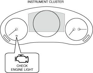
CHECK ENGINE LIGHT
Purpose
-
• If a malfunction occurs in the engine control system, the light illuminates to warn the driver of the malfunction.
Function
-
• The check engine light illuminates when a malfunction occurs in the engine control system, and it illuminates at the same time a DTC is recorded in the PCM.• The PCM sends a check engine light illumination request to the instrument cluster via CAN communication.
Structure/Construction
-
• The check engine light is equipped in the instrument cluster.
 atsuzn00000562• A warning message in the center display is displayed when the check engine light is illuminated or flashes. For the message content and verification method, refer to the [CENTER DISPLAY] in the workshop manual.
Operation
-
• If a malfunction occurs in the engine control system, the PCM sends a check engine light illumination request signal to the instrument cluster.• When the instrument cluster receives the check engine light illumination request signal sent from the PCM as a CAN signal, it turns the check engine light on.• The illumination conditions for the check engine light are determined by the number of drive cycles set for each DTC. For details on the drive cycle, refer to “workshop manual”.
-
― For DTCs with one drive cycle, if a malfunction is detected in the first drive cycle, the check engine light illuminates.― For DTCs with two drive cycles, if each malfunction is detected in the first and second drive cycles, the check engine light illuminates. However, if the same malfunction as the DTC stored in the PCM is detected, the check engine light illuminates in the first drive cycle even if the DTC is two drive cycles.― If the PCM detects that the engine control system is continuously normal for three drive cycles, the illuminated check engine light turns off.
-
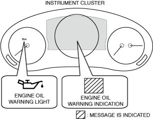
ENGINE OIL WARNING INDICATION/ENGINE OIL WARNING LIGHT
Purpose
-
• The engine oil warning indication/engine oil warning light warns the driver that the engine oil pressure is insufficient.
Function
-
• If the engine oil pressure is low, the PCM sends an engine oil warning indication/engine oil warning light illumination request signal to the instrument cluster.atsuzn00000563• When the instrument cluster receives the engine oil warning indication/engine oil warning light illumination request signal sent from the PCM as a CAN signal, it turns the engine oil warning indication/engine oil warning light on.
Construction
-
• The engine oil warning indication/engine oil warning light is equipped in the instrument cluster.• A warning message is displayed in the multi-information display as the same time the engine oil warning indication is displayed. For the message content and verification method, refer to [MULTI-INFORMATION DISPLAY]. (See MULTI-INFORMATION DISPLAY.)• A warning message in the center display is displayed when the engine oil warning indication/engine oil warning light is illuminated. For the message content and verification method, refer to the [CENTER DISPLAY] in the workshop manual.
Operation
-
Engine oil warning indication
-
1. When the ignition is switched ON (engine off or on), the instrument cluster receives (1) an engine oil warning indication request signal from the PCM or the CMU via CAN communication.2. The instrument cluster displays (2) the engine oil warning indication in the multi-information display.
atsuzn00000506
|

-
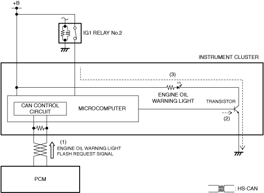
Engine oil warning light
-
1. The instrument cluster receives (1) the engine oil warning light request signal from the PCM.2. The instrument cluster microcomputer turns the transistor on (2) based on the engine oil warning light request signal.3. When the transistor turns on, a ground circuit with the engine oil warning light is established and the engine oil warning light illuminates (3).
atsuzn00000507
|
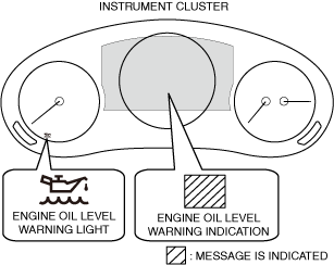
ENGINE OIL LEVEL WARNING INDICATION/ENGINE OIL LEVEL WARNING LIGHT
Purpose
-
• The engine oil level warning indication/warning light warns the driver that the engine oil level is at the MIN position on the oil level gauge, or the engine oil level sensor is malfunctioning.
Function
-
• The PCM sends an engine oil level warning light illumination/warning indication request signal to the instrument cluster.atsuzn00000564• When the instrument cluster receives an engine oil level warning light illumination request signal/engine oil level warning indication request signal sent from the PCM via CAN communication, it turns the engine oil level warning light on or displays the engine oil level warning indication.
Construction
-
• The engine oil level warning indication is displayed in the multi-information display• The engine oil level warning light is built into the instrument cluster.• A warning message is displayed in the center display as the same time the engine oil level warning light is turned on/engine oil level warning indication is displayed. For the message content and verification method, refer to [CENTER DISPLAY] in the workshop manual.
Operation
-
• The condition related to the engine oil level warning light is as follows.
-
― PCM determines that engine oil level is in MIN position on oil level gauge
• The condition related to the engine oil level warning indication is as follows.-
― PCM determines that engine oil level sensor is malfunctioning
-
-
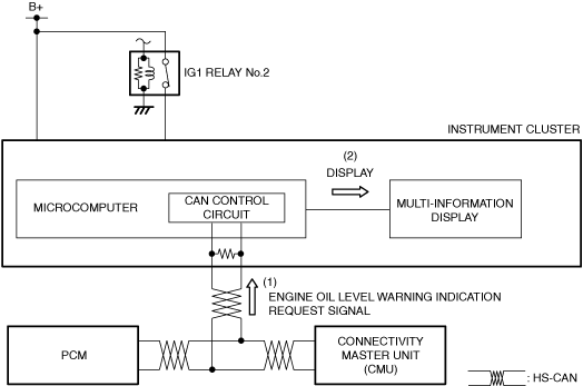
Engine oil level warning indication
-
1. When the ignition is switched ON (engine off or on), the instrument cluster receives (1) an engine oil level warning indication request signal from the PCM via CAN communication.2. The instrument cluster displays (2) the engine oil level warning indication in the multi-information display.
atsuzn00000508
|
-
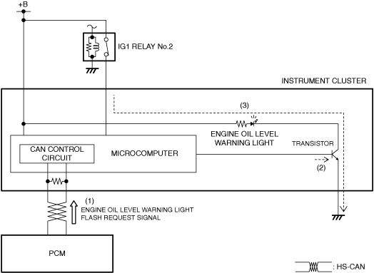
Engine oil level warning light
-
1. When the ignition is switched ON (engine off or on), the instrument cluster receives (1) an engine oil level warning light illumination request signal from the PCM via CAN communication.2. The instrument cluster turns the transistor on (2) based on the engine oil level warning light illumination request signal.3. When the transistor turns on, a ground circuit with the engine oil level warning light is established and the engine oil level warning light turns on (3).
atsuzn00000509
|
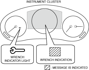
WRENCH INDICATION/WRENCH INDICATOR LIGHT
Purpose
-
• The wrench indication/wrench indicator light notifies the driver that the maintenance period previously set by the driver is approaching, or that the PCM has determined engine oil deterioration.
Function
-
• When a maintenance period previously set by the driver is approaching, or if the PCM determines engine oil deterioration, the PCM sends a wrench indication request signal/wrench indicator light illumination request signal to the instrument cluster.atsuzn00000565• When the instrument cluster receives a wrench indication request signal/wrench indicator light illumination request signal sent from the connectivity master unit (CMU) or the PCM via CAN communication, it turns the wrench indicator light on or displays the wrench indication.
Construction
-
• The wrench indication/wrench indicator light is built into the instrument cluster.• A warning message is displayed in the multi-information display as the same time the wrench indicator light is turned on/wrench indication is displayed. For the message content and verification method, refer to [MULTI-INFORMATION DISPLAY]. (See MULTI-INFORMATION DISPLAY.)• A warning message is displayed in the center display as the same time the wrench indicator light is turned on/wrench indication is displayed. For the message content and verification method, refer to [CENTER DISPLAY] in the workshop manual.
Operation
-
• The wrench warning indicator light illumination conditions are as follows:
-
― When the preset maintenance period is approaching― PCM determines engine oil replacement period reached. (See ENGINE OIL MAINTENANCE MONITOR [SKYACTIV-G (WITHOUT CYLINDER DEACTIVATION (US))].)
-
-
Wrench indication
-
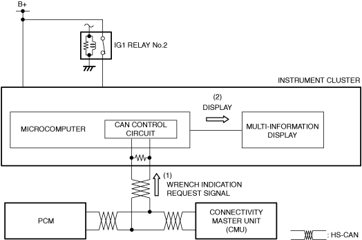
1. When the ignition is switched ON (engine off or on), the instrument cluster receives (1) a wrench indication request signal from the PCM or the CMU via CAN communication.2. The instrument cluster displays (2) the wrench indication in the multi-information display.
atsuzn00000510
|
-
Wrench indicator light
-
1. When the ignition is switched ON (engine off or on), the instrument cluster receives (1) a wrench indicator light illumination request signal from the PCM or the CMU via CAN communication.2. The instrument cluster turns the transistor on (2) based on the wrench indicator light illumination request signal.3. When the transistor turns on, a ground circuit with the wrench indicator light is established and the wrench indicator light turns on (3).
atsuzn00000511
|

GEAR SHIFT INDICATOR
Purpose/Function
-
• The gear shift indicator, built into the instrument cluster, informs the driver that a gear position or shift up/down operation is recommended according to the driving conditions.
-
• The PCM sends a gear shift indicator illumination request to the instrument cluster via CAN communication.
Construction
-
• The gear shift indicator is built into the instrument cluster.atsuzn00000574
Operation
-
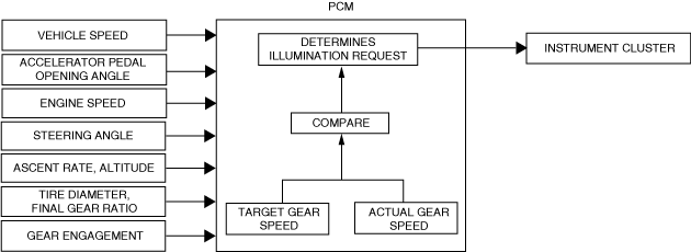
• The PCM compares the target gear speed (calculated from each signal) and the actual gear speed to determine a gear shift indicator illumination request.am2zzn00003727
-
Target gear speed (recommended gear position)
-
― The target gear speed is determined by the vehicle speed, accelerator pedal opening angle, ascent rate, altitude, and steering angle.
-
Actual gear speed (current gear position)
-
The actual gear speed is determined by the vehicle speed, engine speed, tire diameter, final gear ratio, and gear engagement.
-
-
• The gear shift indicator illumination/off conditions are as follows:
-
Gear shift indicator illumination condition
-
• There are three gear shift indicator illumination patterns; normal operation, shift-down recommended operation, and shift-up recommended operation.
-
Normal operation
-
― When the following condition is met, the currently selected gear position is indicated.
-
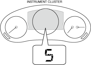
• Target gear speed and actual gear speed are equal
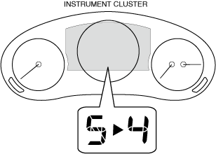
Example: the following figure indicates that the currently selected gear position is 5th gear.
atsuzn00000575
-
-
Shift-down recommended operation
-
― If a shift-down operation is recommended when the following condition is met (determines smooth driveability will be difficult), the recommended gear position is indicated at the same time.
-
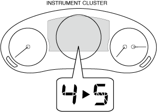
• Target gear speed is lower than actual gear speed
Example: The following figure indicates that a shift-down operation to 4th gear is recommended.
atsuzn00000576
-
-
Shift-up recommended operation
-
― If a shift-up operation is recommended when the following condition is met (determines fuel economy will worsen), the recommended gear position is indicated at the same time.
-
• Target gear speed is higher than actual gear speed
Example: The following figure indicates that a shift-up operation to 5th gear is recommended.
atsuzn00000574
-
-
-
― Vehicle is stopped― Gear is in neutral position or reverse position.― Until clutch is completely engaged when vehicle is started (MTX)― Clutch pedal is depressed for 2 s or more while driving (MTX)
CHECK FUEL CAP WARNING INDICATION/CHECK FUEL CAP WARNING LIGHT
Purpose
-
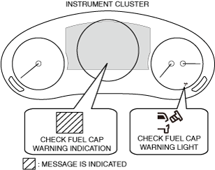
• The check fuel cap warning indication/check fuel cap warning light warns the driver that the fuel cap may not have been closed securely.
Function
-
• When the PCM stores DTC P0457:00 (PCM detects that fuel cap is open), it sends a check fuel cap warning indication/check fuel cap warning light illumination request signal to the instrument cluster. For details on the illumination conditions, refer to “workshop manual“.• Based on the check fuel cap warning indication/check fuel cap warning light illumination request signal sent from the PCM via CAN communication, the instrument cluster turns the check fuel cap warning light on.
Construction
-
• The check fuel cap warning indication/check fuel cap warning light is built into the instrument cluster.atsuzn00000569• A warning message is displayed in the multi-information display as the same time the check fuel cap warning light is turned on/check fuel cap warning indication is displayed. For the message content and verification method, refer to [MULTI-INFORMATION DISPLAY]. (See MULTI-INFORMATION DISPLAY.)• A warning message is displayed in the center display as the same time the check fuel cap warning light is turned on/check fuel cap warning indication is displayed. For the message content and verification method, refer to [CENTER DISPLAY] in the workshop manual.
Operation
-
Check fuel cap warning indication
-
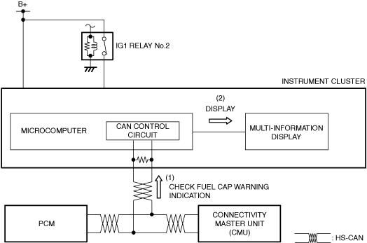
1. When the ignition is switched ON (engine off or on), the instrument cluster receives (1) a check fuel cap warning indication request signal from the PCM or the CMU via CAN communication.2. The instrument cluster displays (2) the check fuel cap warning indication in the multi-information display.
atsuzn00000512
|
-
Check fuel cap warning light
-
1. When the ignition is switched ON (engine off or on), the instrument cluster receives (1) a check fuel cap warning light illumination request signal from the PCM via CAN communication.2. The instrument cluster turns the transistor on (2) based on the check fuel cap warning light illumination request signal.3. When the transistor turns on, a ground circuit with the check fuel cap warning light is established and the check fuel cap warning light turns on (3).
atsuzn00000513
|

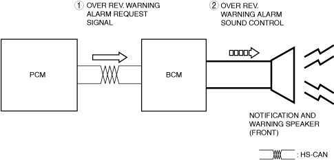
OVER REV. WARNING ALARM
Purpose
-
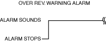
• The over-rev warning alarm notifies the user that the engine speed is too high.
Function
-
• The over rev. warning alarm sound pattern is as shown in the figure.am3uun00003570
Construction
-
• The over rev. warning alarm sounds using the buzzer built into the instrument cluster.
Operation
-
1. When the BCM receives (1) a over rev. warning alarm signal via CAN communication from the Instrument cluster, the BCM sounds the notification and warning speaker (2).
am3zzn00008989
|