HEADLIGHT AUTO LEVELING SYSTEM
HEADLIGHT AUTO LEVELING SYSTEM
SM2334243
id091800010900
Outline
• The headlight auto leveling system automatically adjusts the headlight LO optical axis in response to changes in load and passenger conditions to prevent blinding of oncoming vehicles from headlight glare and to assure a range of visibility.
Function
• The headlight auto leveling system is controlled by the auto leveling control module/adaptive front lighting system(AFS) control module.
Optical axis adjustment function
-
• If there is a vehicle height change with the ignition switched ON (engine on or off) and the headlights LO turned on, the auto leveling control module/AFS control module automatically adjusts the headlight LO optical axis.• The auto leveling control module/AFS control module controls the optical axis adjustment function based on the following signals.
|
Signal name |
Sending module/part name |
Communication method |
|---|---|---|
|
Vehicle speed signal
|
PCM
|
HS-CAN
|
|
Ignition switch position signal
|
Instrument cluster
|
|
|
Headlight LO on condition signal
|
BCM
|
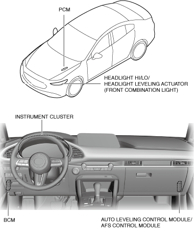
Structure/Construction
System structure
am3zzn00008809
|
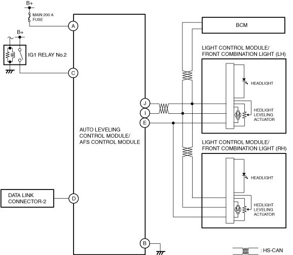
System wiring diagram
am3zzn00008679
|
Operation
Vehicle attitude angle changes while vehicle is stopped
-
Operation conditions
-
• Operates when all of the following conditions are met:
-
― Vehicle speed is 0 km/h {0 mph} ( 0 km/h {0 mph} vehicle speed signal is received)― Ignition is switched ON (engine off or on) (ignition switch position ON signal is received)― Headlights LO on (headlight LO on condition signal reception)― Detects amount of change in vehicle attitude angle at specified value or more
-
-
Operation
-
1. The auto leveling control module/AFS control module calculates (1) the amount of change in the vehicle attitude angle * based on the vehicle attitude angle in the unloaded condition and the vehicle attitude angle detected by the internal acceleration sensor.2. The auto leveling control module/AFS control module calculates (3) the amount of change in the vehicle attitude angle at the specified value or more while it receives (2) a headlight LO on condition signal from the BCM via CAN communication.3. The auto leveling control module/AFS control module calculates (4) the target optical axis based on the calculated amount of change in the vehicle attitude angle.4. The auto leveling control module/AFS control module sends (5) the calculated target optical axis signal to the BCM via CAN communication.5. The BCM sends (6) the calculated target optical axis signal to the front combination light via CAN communication.6. When the front combination light receives the target optical axis signal, it drives (7) the motor.
am3zzn00009320
|
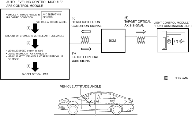
* :The amount of change in the vehicle attitude angle is the calculated value for the vehicle attitude angle information in the unloaded condition recorded by the auto leveling control module/AFS control module for the initial learning and the vehicle attitude angle information detected by the acceleration sensor.
Vehicle attitude angle changes while vehicle is being driven
-
Operation conditions
-
• Operates when all of the following conditions are met:
-
― Vehicle speed is 0 km/h {0 mph} or more (vehicle speed signal of 0 km/h {0 mph} or more is received)― Headlight LO on (headlight LO on condition signal reception)― Detects change in vehicle attitude angle for approx. 20 s― Detects amount of change in vehicle attitude angle * at specified value or more
-
-
Operation
-
1. The auto leveling control module/AFS control module calculates (1) the amount of change in the vehicle attitude angle * based on the vehicle attitude angle in the unloaded condition and the vehicle attitude angle detected by the internal acceleration sensor.2. The auto leveling control module/AFS control module detects change in the vehicle attitude angle for approx. 20 s and calculates (3) the amount of change in the vehicle attitude angle * at the specified value or more while it receives (2) a headlight LO on condition signal from the BCM via CAN communication and the vehicle is being driven at a speed of 0 km/h {0 mph} or more.3. The auto leveling control module/AFS control module calculates (4) the target optical axis based on the calculated amount of change in the vehicle attitude angle.4. The auto leveling control module/AFS control module sends (5) the calculated target optical axis signal to the BCM via CAN communication.5. The BCM sends (6) the calculated target optical axis signal to the front combination light via CAN communication.6. When the front combination light receives the target optical axis signal, it drives (7) the motor.
am3zzn00009321
|
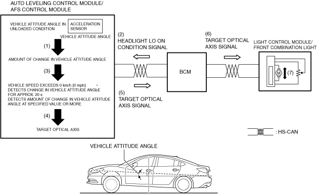
* :The amount of change in the vehicle attitude angle is the calculated value for the vehicle attitude angle information in the unloaded condition recorded by the auto leveling control module/AFS control module for the initial learning and the vehicle attitude angle information detected by the acceleration sensor.