FUEL INJECTION CONTROL SYSTEM [SKYACTIV-G (WITHOUT CYLINDER DEACTIVATION (US))]
FUEL INJECTION CONTROL SYSTEM [SKYACTIV-G (WITHOUT CYLINDER DEACTIVATION (US))]
SM2565330
id0140u0138600
Outline
• Performs optimum fuel injection according to engine operation conditions.
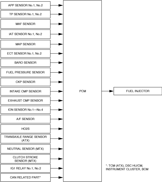
• The PCM determines the engine operation conditions based on the signals from each input device and drives the fuel injectors at the optimal fuel injection time (fuel injection amount) and the fuel injection timing to inject fuel.
• Optimally controls combustion based on fuel injection amount, fuel injection timing, number of fuel injections, and the fuel pressure to achieve emission performance improvement and higher engine output.
Block Diagram
am3zzn00008273
|
Operation
Injection timing
-
• Fuel injection timing is switched according to the engine operation conditions.
-
• Fuel injection is performed at the appropriate injection timing and amount based on the following sensor input signals synchronized with the crankshaft rotation during the intake or compression stroke at each cylinder.
-
― MAF sensor― MAP sensor― IAT sensor No.1― IAT sensor No.2― BARO sensor― CKP sensor― ECT sensor No.1, No.2
-
Injection time
-
• The PCM calculates the fuel injection amount according to the engine operation conditions as the fuel injection time and energizes the fuel injectors.
-
Fuel injector energization time and operation conditions
-
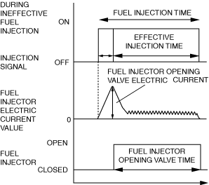
• The fuel injectors cause an operation delay with the start of energization from the PCM. The PCM calculates the fuel injection time by adding the non-injection time (ineffective injection time) due to the operation delay to the actual injection time (effective injection time), and energizes the fuel injectors for this time.
 ac5uun00001135• The fuel injection time is based on the following formula: Fuel injection time = effective injection time + ineffective injection time
-
Ineffective injection time
-
― The fuel injectors cause an operation delay with the start of energization due to a delay in the rise of operation current by coil inductance, mass of the needle valve and plunger, and spring resistance. This delay is the ineffective injection time.― The non-injection time is affected by the change in fuel pressure and the battery voltage. Accordingly, the PCM sets the non-injection time according to the fuel pressure and the battery voltage.
-
Effective injection time
-
― The time when the fuel injector valve is open, which is the actual fuel injection time, is called the effective injection time.
-
Determination of effective injection time
-
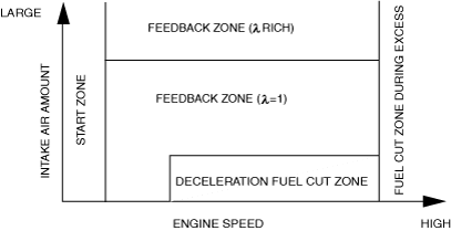
• The PCM divides the engine operation conditions into control zones according to engine speed and intake air amount, and determines the effective injection time at each control zone to perform optimum air/fuel ratio control in all engine driving ranges.am6zzn00002915
Control zone table
|
Control name |
Control outline |
|---|---|
|
Start zone
|
Purpose
• Improved startability
Control condition
• When engine speed is less than 500 rpm
Determination of fuel injection time
• According to engine coolant temperature and engine speed and fuel pressure
|
|
Feedback zone (λ = 1)
|
Purpose
• Improved fuel economy
• Improved exhaust gas purification
Control condition
• During engine operation condition except for engine start zone and feedback zone (λ rich) and fuel cut zone
Determination of fuel injection time
• During normal driving, the various correction amounts are added to the basic injection time during normal driving to obtain a ratio that is close to the theoretical air/fuel ratio.
|
|
Feedback zone (λ rich)
|
Purpose
• Improved driveability
Control condition
• The accelerator pedal opening angle is the specified value or more
Determination of fuel injection time
• Fuel amount increases according to accelerator pedal opening angle
|
|
Purpose
• Protection of catalytic converter and exhaust system components (suppression of gas temperature)
Control condition
• The estimated exhaust temperature and estimated catalytic converter temperature are the specified value or more.
Determination of fuel injection time
• Fuel amount increases according to estimated exhaust gas temperature and estimated catalytic converter temperature (promotion of cooling efficiency from vaporization heat)
|
|
|
Excessive speed fuel cut zone
|
Purpose
• Engine protection
Control condition
• When engine speed is 6,800 rpm or more (SKYACTIV-G 2.0)
• When engine speed is 6,500 rpm or more (SKYACTIV-G 2.5)
• When engine speed is 2,500 rpm or more (When DTC P0089:00 is stored)
Determination of fuel injection time
• Fuel injection stopped.
|
|
Deceleration fuel cut zone
|
Purpose
• Improved fuel economy
Control condition
• If all of the following conditions are met while the vehicle is decelerating
Determination of fuel injection time
• Fuel injection is stopped.
|
Fuel injection time calculation method table
(A: Fuel injection time base, B: Correction for fuel injection time)
|
Contents
(Calculation or determination method for fuel injection time and correction)
|
Control zone
|
||||||
 |
 |
 |
 |
 |
|||
|
Injection time at engine start
|
Set value according to engine coolant temperature (low engine coolant temperature→long injection time)
|
A
|
|||||
|
Basic injection time
|
Basic injection time = Charging efficiency *1 × fuel flow coefficient*2
|
A
|
A
|
||||
|
Fuel cut
|
Fuel injection time = 0
|
A
|
A
|
||||
|
Ineffective injection time
|
Set time according to fuel injector performance
|
A
|
A
|
A
|
|||
|
Volume increase correction at engine start
|
Purpose: Ensures engine speed stability just after engine start
Correction condition
• Specified time according to engine coolant temperature directly after engine start
Correction amount
• Low engine coolant temperature→large correction
• Low intake air temperature→large correction
|
B
|
B
|
||||
|
Feedback correction (A/F sensor)
|
Purpose: Controls air/fuel ratio to theoretical air/fuel ratio
Correction amount
• A/F sensor output current is 0 mA or less→volume decrease correction
• A/F sensor output current is 0 mA or more→volume increase correction
|
B
|
B
|
||||
|
Feedback correction (HO2S)
|
Purpose: Controls air/fuel ratio to theoretical air/fuel ratio
Correction amount
• HO2S output voltage is approx. 0.7 V or more→volume decrease correction
• HO2S output voltage is approx. 0.7 V or less→volume increase correction
|
B
|
|||||
|
Warm-up volume increase correction
|
Purpose: Ensures combustion stability when engine coolant temperature is low
Correction condition
• When engine coolant temperature is at set value
Correction amount
• High charging efficiency, low engine coolant temperature→large correction
|
B
|
B
|
||||
|
Learning correction
|
Purpose: Corrects deviation in air/fuel ratio from deterioration over time of mechanical devices
Correction amount
• Learned value based on average value of A/F deviation amount (feedback amount)
|
B
|
B
|
||||
|
Heavy load volume increase correction
|
Purpose: Improved engine output, decrease of exhaust gas temperature
Correction condition
• Based on the fixed value when the accelerator pedal opening angle is a certain value or more, otherwise, based on engine speed and charging efficiency.
Correction amount
• High engine speed, high charging efficiency→large correction
|
B
|
|||||
*1:Charging efficiency is the ratio of the actual amount of intake air to the maximum air charging amount (mass volume) of the cylinder. The value increases as the engine load increases.
*2:Fuel flow coefficient is a coefficient to calculate a fuel injection time from a fuel injection amount required for an intake air amount.
Fuel cut
-
• Includes fuel cut under the following conditions, except fuel cut at excessive engine speed and deceleration fuel cut according to engine operation.
Fuel cut table
|
Control name |
Control outline |
|---|---|
|
Fuel cut during selector lever shifting in D range
|
Purpose
• ATX protection
Control conditions
• When shifting while vehicle is stopped and engine raced
|
|
Sensor malfunction fuel cut
|
Purpose
• To prevent engine damage from abnormal ignition due to a malfunction input of a cylinder identification or the engine speed signal.
Control conditions
• When a malfunction in the crankshaft position sensor or exhaust camshaft position sensor is detected
|
|
Dechoke control
|
Purpose
• To improve engine startability when spark plugs are flooded (scavenging)
Control conditions
• When cranking close to fully-open throttle valve
|
|
Theft prevention
|
Purpose
• To prevent theft
Control conditions
• Immobilizer system related information (engine start prohibited) received from BCM
|
|
Fuel-cut at time of collision
|
Purpose
• For safety assurance
Control conditions
• Collision signal from SAS control module is received
|
|
Fuel cut during engine rotation resonance caused by dual-mass flywheel
(SKYACTIV-G 2.0 (MTX))
|
Purpose
• To prevent engine damage due to engine rotation resonance caused by dual-mass flywheel
Control conditions
• Engine rotation resonance caused by dual-mass flywheel is detected (extremely low engine speed range lowering idle speed)
|
Boost Circuit
-
• The battery positive voltage input via the sub relay is boosted up to 60 V.
Output Circuit
-
• To improve fuel injection response, the plunger pulling force is strengthened by providing high current (over excitation current) when the fuel injector is open.• To reduce fuel injector heat generation, the opening of the fuel injector is kept open using low current after it opens.
|
Fuel injector status |
PCM operation |
|---|---|
|
Opening starts
|
1. Provides specified value, boosted by the boost circuit, to the opening transistor.
2. Voltage is provided to the fuel injector, the ground transistor is turned on and grounded, and the fuel injector opens.
3. After the fuel injector is opened, the opening transistor is turned off.
|
|
Opening held
|
• Controls the on/off of the holding transistor (12 V output) so that the hold current of the fuel injector is constant.
|
|
Closing
|
• Turns off the holding and ground transistors at the same time the fuel injection signal from the PCM is stopped, and cuts the current.
|