DSC HU/CM [(US)]
DSC HU/CM [(US)]
SM2565405
id0415001033x1
Outline
ac5wzn00000226
|
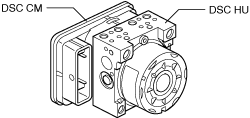
DSC HU Part Purpose/Function
DSC HU Part Construction
Function of main component parts
|
Part name |
Function |
|---|---|
|
Inlet solenoid valve
|
• Adjusts the fluid pressure in each brake system according to DSC HU/CM signals.
|
|
Outlet solenoid valve
|
• Adjusts the fluid pressure in each brake system according to DSC HU/CM signals.
|
|
Stability control solenoid valve
|
• Switches the brake hydraulic circuits during and according to normal braking, ABS and EBD control, TCS control, DSC control, and brake assist control.
|
|
Traction control solenoid valve
|
• Switches the brake hydraulic circuits during and according to normal braking, ABS and EBD control, TCS control, DSC control, and brake assist control.
|
|
Reservoir
|
• Temporarily stores brake fluid from the caliper piston to ensure smooth pressure reduction during ABS and EBD control, TCS control, and DSC control.
|
|
Pump
|
• Returns the brake fluid stored in the reservoir to the master cylinder during ABS and DSC control.
• Increases brake fluid pressure and sends brake fluid to each caliper piston during TCS control and DSC control.
|
|
Pump motor
|
• Operates the pump according to DSC HU/CM signals.
|
ac5wzn00000227
|
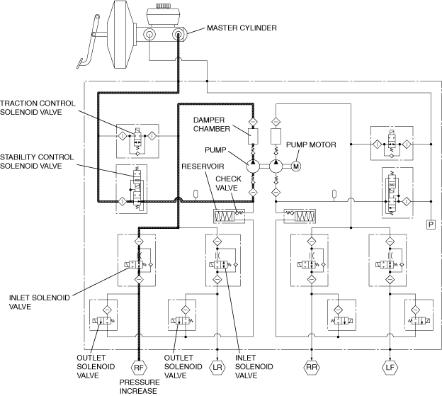
DSC HU Part Operation
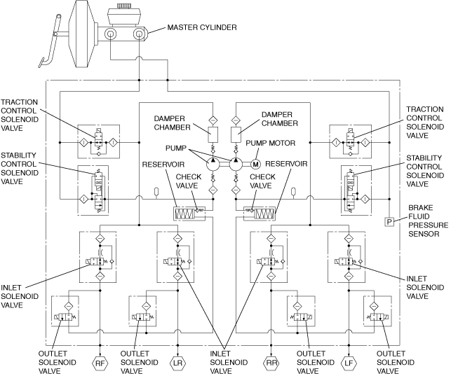
During normal braking
-
• During normal braking, the solenoid valves are not energized and all of them are off. When the brake pedal is depressed, brake fluid pressure is transmitted from the master cylinder, through the traction control solenoid and inlet solenoid valves, and then to the caliper piston.
Solenoid valve operation table
|
Traction control solenoid valve |
Stability control solenoid valve |
Inlet solenoid valve |
Outlet solenoid valve |
Pump motor, pump |
||||||||
|---|---|---|---|---|---|---|---|---|---|---|---|---|
|
LF―RR |
RF―LR |
LF―RR |
RF―LR |
LF |
RF |
LR |
RR |
LF |
RF |
LR |
RR |
|
|
OFF (open)
|
OFF (closed)
|
OFF (open)
|
OFF (closed)
|
Stopped
|
||||||||
Hydraulic Circuit Diagram
ac5wzn00001068
|
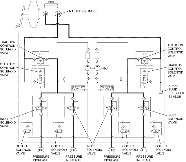
During ABS and EBD control
-
• During ABS and EBD control when wheel lock-up is about to occur, the traction control solenoid and stability control solenoid valves are not energized, and the inlet and outlet solenoid valves are energized and controlled in three pressure modes (increase, reduction or maintain), thereby adjusting brake fluid pressure. Brake fluid during pressure reduction is temporarily stored in the reservoir and afterwards the pump motor operates the pump to return the fluid to the master cylinder. (The following figure shows these conditions: right front wheel pressure increased, left front wheel pressure maintained, and both rear wheels pressure decreased.)
Solenoid valve operation table
|
|
Traction control solenoid valve |
Stability control solenoid valve |
Inlet solenoid valve |
Outlet solenoid valve |
Pump motor, pump |
||||||||
|---|---|---|---|---|---|---|---|---|---|---|---|---|---|
|
LF―RR |
RF―LR |
LF―RR |
RF―LR |
LF |
RF |
LR |
RR |
LF |
RF |
LR |
RR |
||
|
During pressure increase mode
|
OFF (open)
|
OFF (closed)
|
OFF (open)
|
OFF (closed)
|
Stopped
|
||||||||
|
During pressure maintain mode
|
OFF (open)
|
OFF (closed)
|
ON (closed)
|
OFF (closed)
|
Stopped
|
||||||||
|
During pressure reduction mode
|
OFF (open)
|
OFF (closed)
|
ON (closed)
|
ON (open)
|
Operating
|
||||||||
Hydraulic Circuit Diagram
ac5wzn00000943
|
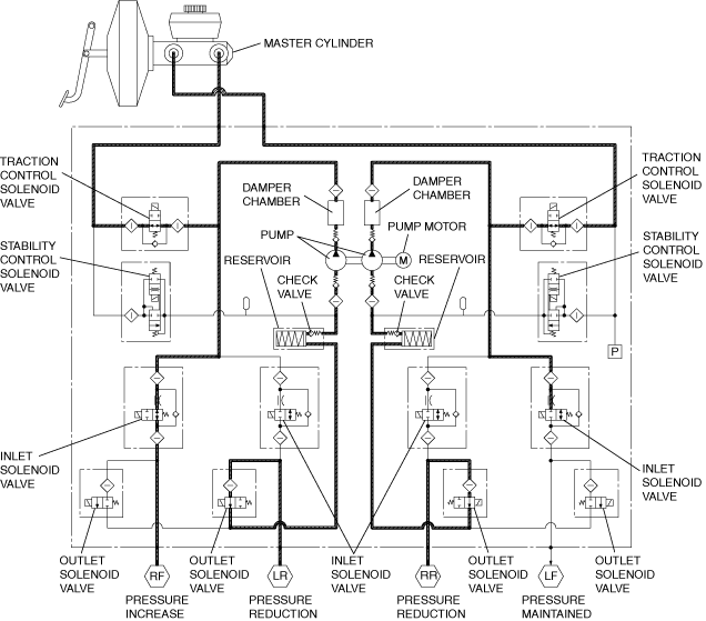
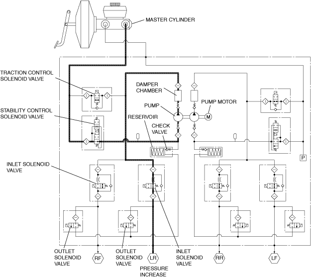
During DSC control (to suppress oversteer tendency) and TCS control
-
• When a large oversteer tendency or driving wheel spin is determined, the traction control solenoid and stability control solenoid valves are energized, switching the hydraulic circuits. At the same time, the pump motor is actuated to operate the pump, thereby increasing pressure by supplying brake fluid pressure to the caliper piston of the outer front wheel or the slipping driving wheel. Also at this time, the inlet solenoid valve of the inner rear wheel is energized and the hydraulic circuit of this wheel is closed.• After a pressure increase, brake fluid pressure is adjusted using the three pressure modes (reduction, maintain, increase) so that the target wheel speed is obtained. (The following figure shows a left turn, or control of right front wheel spin (during pressure increase mode).)
Solenoid valve operation table
|
|
Traction control solenoid valve |
Stability control solenoid valve |
Inlet solenoid valve |
Outlet solenoid valve |
Pump motor, pump |
||||||||
|---|---|---|---|---|---|---|---|---|---|---|---|---|---|
|
LF―RR |
RF―LR |
LF―RR |
RF―LR |
LF |
RF |
LR |
RR |
LF |
RF |
LR |
RR |
||
|
During pressure increase mode
|
OFF
(open)
|
ON
(closed)
|
OFF (closed)
|
ON
(open)
|
OFF
(open)
|
ON
(closed)
|
OFF
(open)
|
OFF (closed)
|
Operating
|
||||
|
During pressure maintain mode
|
OFF
(open)
|
ON
(closed)
|
OFF (closed)
|
OFF
(open)
|
ON
(closed)
|
OFF
(open)
|
OFF (closed)
|
Stopped
|
|||||
|
During pressure reduction mode
|
OFF
(open)
|
ON
(closed)
|
OFF (closed)
|
OFF
(open)
|
ON
(closed)
|
OFF
(open)
|
OFF
(closed)
|
ON
(open)
|
OFF
(closed)
|
Operating
|
|||
Hydraulic Circuit Diagram
ac5wzn00000230
|
During DSC control (to suppress understeer tendency)
-
• When a large understeer tendency is determined, the traction control solenoid and stability control solenoid valves are energized, switching the hydraulic circuits. At the same time, the pump motor is actuated to operate the pump, supplying brake fluid pressure from the reservoir to the inner rear caliper piston. Also at this time, the inlet solenoid valve of the outer front wheel is energized and the hydraulic circuit of this wheel is closed.• After a pressure increase, brake fluid pressure is adjusted using the three pressure modes (reduction, maintain, increase) so that the target wheel speed is obtained. (The following figure shows control during a left turn during pressure increase mode.)
Solenoid valve operation table
|
|
Traction control solenoid valve |
Stability control solenoid valve |
Inlet solenoid valve |
Outlet solenoid valve |
Pump motor, pump |
||||||||
|---|---|---|---|---|---|---|---|---|---|---|---|---|---|
|
LF―RR |
RF―LR |
LF―RR |
RF―LR |
LF |
RF |
LR |
RR |
LF |
RF |
LR |
RR |
||
|
During pressure increase mode
|
OFF
(open)
|
ON
(closed)
|
OFF
(closed)
|
ON
(open)
|
OFF
(open)
|
ON
(closed)
|
OFF
(open)
|
OFF (closed)
|
Operating
|
||||
|
During pressure maintain mode
|
OFF
(open)
|
ON
(closed)
|
OFF (closed)
|
OFF
(open)
|
ON
(closed)
|
OFF
(open)
|
OFF (closed)
|
Stopped
|
|||||
|
During pressure reduction mode
|
OFF
(open)
|
ON
(closed)
|
OFF (closed)
|
OFF
(open)
|
ON
(closed)
|
OFF
(open)
|
OFF
(closed)
|
ON
(open)
|
OFF
(closed)
|
Operating
|
|||
Hydraulic Circuit Diagram
ac5wzn00000231
|
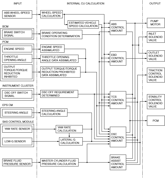
DSC CM Part Function
Function table
|
Function name |
Contents |
|---|---|
|
ABS control function
|
• Controls brake fluid pressure when braking to maintain directional stability, ensure steerability, and reduce stopping distance.
|
|
Electronic brakeforce distribution (EBD) control function
|
• Constantly controls proper distribution of brake fluid pressure to the front and rear wheels according to vehicle load, road surface, and vehicle speed conditions to prevent early lock-up of the rear wheels.
|
|
TCS control function
|
• Controls traction to within the road surface friction limit and according to road and driving conditions to improve starting and acceleration performance, and safety.
|
|
DSC control function
|
• Suppresses strong over-steer and under-steer tendencies when turning by controlling engine output and braking of each wheel to assure driving safety.
|
|
Brake assist control function
|
• The brake pedal depression speed and force is calculated from the brake fluid pressure sensor signal. If it exceeds the specification, an emergency braking situation is determined and a higher amount of hydraulic pressure than the normal specified amount is generated in the hydraulic unit and supplied to each wheel based on the activation of each solenoid valve, pump motor, and pump.
• If a condition is detected in which emergency braking is anticipated by the change in speed of the accelerator pedal position, the gap between the brake pad and disc plate is reduced to enhance the response when braking.
|
|
Hill launch assist (HLA) control function
|
• For detailed information on the hill launch assist (HLA), refer to HILL LAUNCH ASSIST (HLA). (See HILL LAUNCH ASSIST (HLA).)
|
|
CAN communication function
|
• Outputs the vehicle speed signal and DSC system warning control data via CAN lines.
|
|
On-board diagnostic system
|
• A function that allows important parts of the DSC control system to perform self-diagnosis. In case a malfunction occurs, the warning lights illuminate to alert the driver, and at the same time a DTC is stored in the DSC HU/CM.
• When a malfunction is determined as a result of the on-board diagnostic test, system control is suspended or limited to prevent any dangerous situation while driving.
|
|
Automatic configuration function
|
• When the ignition is switched to ON or the engine is started after the DSC HU/CM have been replaced, the DSC CM reads data from the instrument cluster via CAN communication to perform automatic configuration.
|
Block diagram
am3zzn00008810
|
Brake Fluid Pressure Sensor
Purpose/function
-
• The brake fluid pressure sensor detects the fluid pressure from the master cylinder and transmits it to the DSC HU/CM.
Construction
-
• The brake fluid pressure sensor is built into the DSC HU/CM. Therefore if there is any malfunction of the brake fluid pressure sensor, replace the DSC HU/CM.