WARNING/INDICATION/ALARM [DYNAMIC STABILITY CONTROL (DSC) (US)]
WARNING/INDICATION/ALARM [DYNAMIC STABILITY CONTROL (DSC) (US)]
SM2334038
id0415001085x3
Brake System/ABS Warning Light
Purpose/function
-
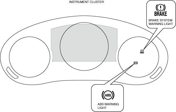
• The brake system warning light is built into the instrument cluster, and if a malfunction occurs in the system, the light turns on to warn the driver of the malfunction.• The ABS warning light turns on to alert the driver if the ABS has a malfunction.
Construction
-
• The brake system warning light and ABS warning light are built into the instrument cluster.
 ac5wzn00004065
Operation
-
Note
-
• If the DSC system and CAN lines are normal, the brake system warning light and ABS warning light turn on when the ignition is switched ON, and turns off after approx. 3 s to check for bulb burn-out. At this time, the brake system warning light remains turned on while the parking brake is applied. However, the light turns off when the parking brake is released.• The DSC HU/CM disables the following controls if there is a system malfunction and the brake system warning light and ABS warning light turn on.
-
ABS warning light turned on:
-
― ABS control disabled
-
ABS warning light and brake system warning light turned on:
-
― ABS control and EBD control disabled
• A warning message is indicated on the center display when the ABS warning light is turned on. For the message content and verification method, refer to the [CENTER DISPLAY] in the workshop manual. -
-
Brake system warning light
-
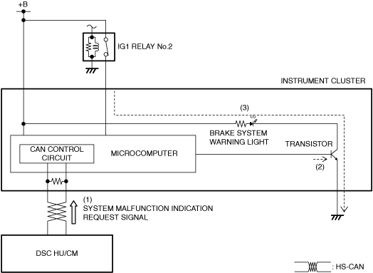
• The instrument cluster receives (1) a system malfunction indication request signal from the DSC HU/CM via CAN communication.• The instrument cluster turns the transistor on (2) based on the system malfunction indication request signal.• When the transistor turns on, the brake system warning light turns on (3).
am3zzn00008640
|
-
ABS warning light
-
• The instrument cluster receives (1) a system malfunction indication request signal from the DSC HU/CM via CAN communication.• The instrument cluster turns the transistor on (2) based on the system malfunction indication request signal.• When the transistor turns on, the ABS warning light turns on (3).
am3zzn00008641
|

AUTOHOLD Active Indicator Light
Purpose/function
-
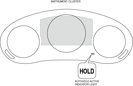
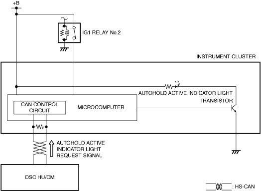
• The AUTOHOLD active indicator light, built into the instrument cluster, notify the driver that the AUTOHOLD is operating.
am3zzn00007922
|
Construction/operation
-
• The AUTOHOLD active indicator light is built into the instrument cluster.• When the DSC HU/CM operates the AUTOHOLD, it sends the AUTOHOLD active indicator light request signal. When the instrument cluster receives the AUTOHOLD active indicator light request signal from the DSC HU/CM, the microcomputer turns the transistor on and a ground circuit with the AUTOHOLD active indicator light is established. Therefore, the AUTOHOLD active indicator light illuminates.
am3zzn00008642
|
TCS/DSC Indicator Light
Purpose/function
-
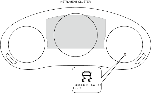
• The TCS/DSC indicator light, built into the instrument cluster, informs the driver of the following vehicle conditions.
-
― TCS is operating. (Drive wheel is slipping.)― DSC is operating. (Vehicle side-slip condition.)― DSC system malfunction.
-
ac5uun00002893
|
Operation
1.The instrument cluster receives (1) the system condition display request signal from the DSC HU/CM via CAN communication.
2.The instrument cluster turns the transistor on, or turns it on intermittently (2) based on the system condition display request signal.
3.When the transistor turns on, the brake system warning lights/ABS warning light turns on or flashes (3).
-
• When the DSC system and CAN lines are normal, the TCS/DSC indicator light illuminates for approx. 3.0 s when the ignition is switched to ON to check the light function. When the system is malfunctioning, the TCS/DSC indicator light remains illuminated.• When the TCS or DSC are non-operational, operational and malfunctioning, the TCS/DSC indicator light operates according to the following table.
TCS/DSC indicator light operation
|
Item |
TCS/DSC indicator light |
|---|---|
|
TCS and DSC not operating
|
Not illuminated
|
|
TCS operating
|
Flashes ( 0.5 s intervals)
|
|
DSC operating
|
|
|
DSC system malfunction
|
Illuminated
|
am3zzn00008643
|

DSC OFF Switch, DSC OFF Indicator Light
Purpose
-
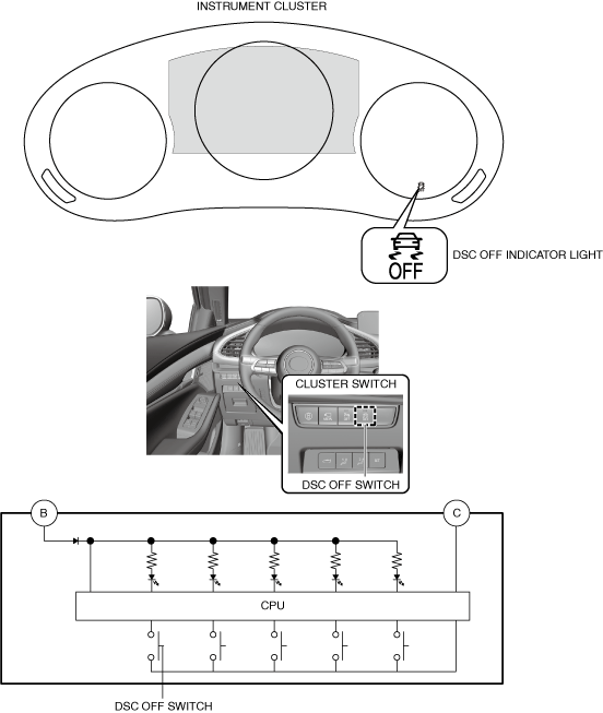
• The DSC OFF switch allows for optionally enabling/disabling the DSC control at the driver’s discretion.• The DSC OFF indicator light notifies the driver that DSC control has been disabled by operation of the DSC OFF switch.
Function
-
• The DSC OFF switch sends a switch operation signal to the instrument cluster.• The instrument cluster turns on the DSC OFF indicator light based on the system condition display request signal sent via CAN communication from the DSC HU/CM.• The DSC OFF indicator light illumination and TCS/DSC control conditions while operating the DSC OFF switch are as indicated in the table.• When the DSC system and CAN lines are functioning normally, the DSC OFF indicator light turns on for approx. 3 s when the ignition is switched ON.• When the DSC OFF switch is pressed to disable the DSC control, the DSC OFF indicator light turns on.
-
Note
-
• To inhibit the DSC control, continue to press the DSC OFF switch until the DSC OFF indicator light illuminates.
-
• The DSC OFF indicator light illumination and TCS/DSC control conditions while operating the DSC OFF switch are as indicated in the table.
|
|
DSC OFF indicator light illumination conditions |
TCS control conditions |
DSC control conditions |
|
|---|---|---|---|---|
|
Brake control |
Engine control |
|||
|
TCS/DSC ON
|
Not illuminated
|
Permitted
|
Permitted
|
Permitted
|
|
TCS/DSC OFF
|
Illuminated
|
Permitted
|
Inhibited
|
Inhibited
|
Construction
-
• The DSC OFF switch is located on the dashboard (cluster switch).• The DSC OFF indicator light is built into the instrument cluster.am3zzn00007167
Operation
-
DSC OFF switch
-
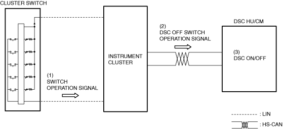
1. When the DSC OFF switch is operated, a switch operation signal is sent (1) to the instrument cluster.2. Based on the switch operation signal, the instrument cluster sends (2) the DSC OFF switch operation signal to the DSC HU/CM via CAN communication.3. The DSC HU/CM switches (3) the DSC ON/OFF when it receives the DSC OFF switch operation signal from the instrument cluster.
am3zzn00008838
|
-
DSC OFF indicator
-
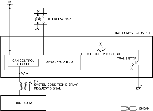
1. The instrument cluster receives (1) the system conditions display request signal from the DSC HU/CM via CAN communication.2. The instrument cluster turns the transistor on (2) based on the system condition display request signal.3. When the transistor turns on, the DSC OFF indicator light turns on (3).
-
Note
-
• When the DSC system and CAN lines are functioning normally, the DSC OFF indicator light turns on for approx. 3 s when the ignition is switched ON.• When the DSC OFF switch is pressed to disable the DSC control, the DSC OFF indicator light turns on.am3zzn00008645
AUTOHOLD Warning Beep
Purpose/function
-
• Notifies the driver that the brake pedal is not depressed to prevent a mis-operation or accident.
Construction/operation
-
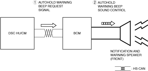
• If there is a problem with the AUTOHOLD function and the electric parking brake while AUTOHOLD is operating without depressing brake pedal, the AUTOHOLD warning beep sounds.• The AUTOHOLD warning beep is activated by the notification and warning speaker.• The DSC HU/CM sends (1) an AUTOHOLD warning beep request signal via CAN communication.• When the BCM receives the AUTOHOLD warning beep request signal, the AUTOHOLD warning beep is activated (2) from the notification and warning speaker.• When the driver operates the brake pedal and the brake fluid pressure is the specification or more, the AUTOHOLD warning beep stops.
am3zzn00008629
|