MAZDA RADAR CRUISE CONTROL (MRCC) SYSTEM [(US)]
MAZDA RADAR CRUISE CONTROL (MRCC) SYSTEM [(US)]
SM2833166
id1510000020a3
Outline
-
Warning
-
• Do not rely completely on the MRCC system and always drive carefully. There are limitations to the distance between the vehicles which can be controlled by the MRCC system, and if the accelerator pedal or brake pedal is mistakenly operated it could result in an accident. Always verify the safety of the surrounding area and depress the brake pedal while keeping a safe distance from the vehicle ahead.• The MRCC system does not completely stop the vehicle using the automatic braking operation. Additionally, brake control is performed, however, there are limitations to the deceleration, and the system may be unable to decelerate sufficiently to avoid hitting the vehicle ahead if the vehicle ahead applies the brakes suddenly or another vehicle cuts into the driving lane, which could result in an accident. Always verify the safety of the surrounding area and depress the brake pedal while keeping a safe distance from the vehicle ahead.
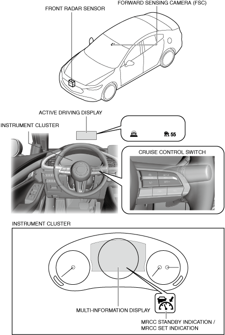
Structural View
am3zzn00008609
|
Functions
-
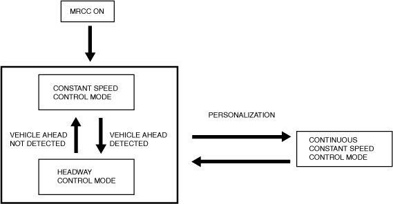
― Constant speed control mode: Drives the vehicle at the set vehicle speed set by the driver based on the cruise control switch operation signal.― Headway control mode: When a vehicle ahead is detected while the vehicle is traveling in constant speed control mode, headway control with the vehicle ahead is performed while maintaining the set distance between the vehicles using the distance between vehicles setting function.
Mode switching function
-
• The modes in the Mazda Radar Cruise Control (MRCC) system can be switched as follows.
-
Note
-
• When switching from constant speed control mode/headway control mode to normal constant speed control mode, the set vehicle speed must be reset. In addition, when switching from normal constant speed control mode to constant speed control mode/headway control mode, the vehicle speed becomes the speed set before switching from normal constant speed control mode.
 am3zzn00008919
Distance between vehicles setting function
-
• Using the DISTANCE switch on the cruise control switch, the distance between vehicles can be controlled at 4 levels, including long→medium→short→extremely short. (Initial setting is set to LONG)am3zzn00008920

-
Caution
-
• The distances between vehicles indicated below are average values during travel on flat roads and differ depending on the driving and road conditions.
Distance between vehicles table (reference)
|
Set distance between vehicles |
Monitoring vehicle speed |
|||||
|---|---|---|---|---|---|---|
|
30 km/h {19 mph} |
40 km/h {25 mph} |
50 km/h {31 mph} |
60 km/h {37 mph} |
70 km/h {43 mph} |
80 km/h {50 mph} |
|
|
Long
|
24 m
{79 ft}
|
30 m
{99 ft}
|
37 m
{122 ft}
|
43 m
{142 ft}
|
49 m
{161 ft}
|
56 m
{184 ft}
|
|
Medium
|
20 m
{66 ft}
|
26 m
{86 ft}
|
31 m
{102 ft}
|
36 m
{119 ft}
|
41 m
{135 ft}
|
46 m
{151 ft}
|
|
Short
|
18 m
{60 ft}
|
22 m
{73 ft}
|
25 m
{83 ft}
|
29 m
{96 ft}
|
32 m
{105 ft}
|
35 m
{115 ft}
|
|
Extremely short
|
17 m
{56 ft}
|
19 m
{63 ft}
|
22 m
{73 ft}
|
24 m
{79 ft}
|
26 m
{86 ft}
|
28 m
{92 ft}
|
|
Set distance between vehicles |
Monitoring vehicle speed |
|||||
|---|---|---|---|---|---|---|
|
90 km/h {56 mph} |
100 km/h {62 mph} |
110 km/h {68 mph} |
120 km/h {75 mph} |
130 km/h {81 mph} |
140 km/h {87 mph} |
|
|
Long
|
62 m
{204 ft}
|
68 m
{224 ft}
|
75 m
{247 ft}
|
81 m
{266 ft}
|
87 m
{286 ft}
|
94 m
{309 ft}
|
|
Medium
|
51 m
{168 ft}
|
56 m
{184 ft}
|
62 m
{204 ft}
|
67 m
{220 ft}
|
72 m
{237 ft}
|
77 m
{253 ft}
|
|
Short
|
39 m
{128 ft}
|
42 m
{138 ft}
|
46 m
{151 ft}
|
49 m
{161 ft}
|
52 m
{171 ft}
|
56 m
{184 ft}
|
|
Extremely short
|
31 m
{102 ft}
|
33 m
{109 ft}
|
35 m
{115 ft}
|
37 m
{122 ft}
|
39 m
{128 ft}
|
42 m
{138 ft}
|
System conditions display function
-
• The body control module (BCM) displays the system status using the MRCC standby indication/MRCC set indication/MRCC warning indication, active driving display/multi-information display, and center display.
|
Condition |
MRCC standby indication |
MRCC set indication |
i-ACTIVSENSE warning indication |
Multi-information display indication (Instrument cluster) |
Active driving display indication |
||
|---|---|---|---|---|---|---|---|
|
MRCC system is OFF
|
Off
|
Off
|
Off
|
No display
|
No display
|
||
|
MRCC system is ON
|
MRCC system is on standby
|
On
|
Off
|
Off
|
 |
 |
|
|
Vehicle speed is set
|
Off
|
On
|
Off
|
 |
 |
||
|
Vehicle ahead is detected
|
Off
|
On
|
Off
|
 |
 |
||
|
MRCC system is ON
|
Distance between vehicles
|
Long
|
Off
|
On
|
Off
|
 |
 |
|
Medium
|
Off
|
On
|
Off
|
 |
 |
||
|
Short
|
Off
|
On
|
Off
|
 |
 |
||
|
Extremely short
|
Off
|
On
|
Off
|
 |
 |
||
|
Accelerator pedal is depressed
|
On
|
Off
|
Off
|
No display
|
No display
|
||
|
Shift up/down required
|
Off
|
Off
|
Off
|
 |
 |
||
|
Deceleration exceeding system limits required
|
Off
|
On
|
Off
|
 |
No display
|
||
|
MRCC system is automatically canceled due to low vehicle speed
|
On
|
Off
|
On
|
 |
No display
|
||
|
MRCC system temporarily off due to related unit condition
|
Off
|
Off
|
On
|
 |
No display
|
||
|
MRCC system off without driver’s intention
|
Off
|
Off
|
Off
|
 |
 |
||
|
MRCC system is ON
|
Malfunction occurred in MRCC system
|
Off
|
Off
|
On
|
 |
No display
|
|
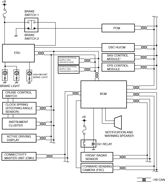
System Wiring Diagram
am3zzn00009077
|
Block Diagram
am3zzn00008611
|

Operation
-
Operation condition
-
― Shift lever is in reverse position or position other than neutral― Vehicle speed is within range of approx. 30—145 km/h {19.0—90.0 mph}― MRCC system is ON― Brake pedal is not depressed― Clutch pedal is not depressed― DSC is not operating― Smart brake support (SBS) is not operating― The Electric Parking Brake (EPB) is released (Electric Parking Brake (EPB) indicator light is turned off)― All doors are closed― Driver seat belt is fastened― No malfunction in DSC system (No DTCs stored in memory)― No malfunction in MRCC system (No DTCs stored in memory)― No malfunction in PCM system (No DTCs stored in memory)
Constant speed control mode
-
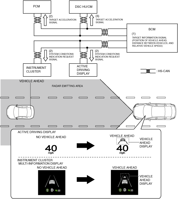
1. The body control module (BCM) recognizes the set vehicle speed set by the driver based on the cruise control switch operation signal (1) sent from the instrument cluster when the operation conditions are met.2. When the body control module (BCM) recognizes the set vehicle speed, it sends a set vehicle speed signal (2) and system condition signal (2) to the instrument cluster and active driving display.3. The body control module (BCM) sends a target acceleration signal (3) to the PCM based on the set vehicle speed signal.4. The PCM performs engine control to maintain the set vehicle speed based on the target acceleration signal (3) from the body control module (BCM). If the PCM judges that can not perform target acceleration, it sends the target acceleration signa (4)l to the DSC HU/CM.5. The instrument cluster and active driving display display the system operation screen based on the set vehicle speed signal (2) and system condition signal (2) from the body control module (BCM).
-
Note
-
• If the vehicle speed decreases to 20 km/h {12 mph} or less while in constant speed control mode, the body control module (BCM) cancels constant speed control mode and switches to standby status.• When the front radar sensor and forward sensing camera (FSC) detect a vehicle ahead, constant speed control mode switches to headway control mode.
am3zzn00009187
|
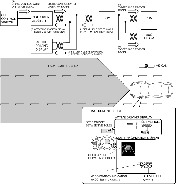
Headway control mode
-
1. When the front radar sensor and forward sensing camera (FSC) detects the target information while the vehicle is traveling in constant speed control mode, it sends the target information signal to the body control module (BCM), and switches the mode to headway control mode.2. The body control module (BCM) calculates (1) the target acceleration based on the following, and sends the target acceleration signal (2) to the PCM. Additionally, it sends the system conditions indication request signal (2) to the instrument cluster and active driving display.
-
― Distance between vehicles set by driver― Target information (Detecting vehicle speed, distance between vehicles, relative speed)― Vehicle speed
3. The PCM performs engine control based on the target acceleration speed signal (2) from the body control module (BCM). If the PCM determines that the target acceleration speed cannot be achieved by engine control only, it sends a target acceleration speed signal (3) to the DSC HU/CM.4. The DSC HU/CM performs brake control based on the target acceleration speed signal (3) from the PCM.5. The instrument cluster displays the vehicle ahead screen on the multi-information display based on the system status display request signal (2) from the body control module (BCM).6. The active driving display displays the vehicle ahead screen based on the system status display request signal (2) from the body control module (BCM). -
-
Note
-
• In the following cases, the system transitions from headway control mode to constant speed mode.
-
― Vehicle ahead accelerates over set vehicle speed of detecting vehicle― Vehicle ahead or detecting vehicle switches driving lanes, and vehicle ahead of detecting vehicle no longer exists
-
am3zzn00009078
|
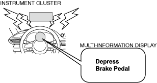
Inter-vehicle distance limit warning
-
• If the following condition is met, the warning alarm in the instrument cluster is activated and the brake warning on the display is indicated to urge the driver to take action such as braking.am3zzn00008926
-
― Body control module (BCM) determines that collision with vehicle ahead is unavoidable even if brake control by SBS system is performed at maximum possible deceleration speed
-
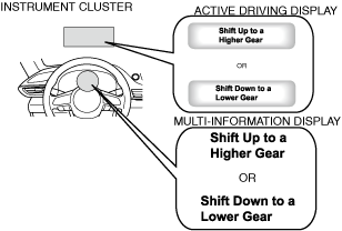
Shift up/shift down request
-
• If the transaxle gear position is not appropriate to the vehicle speed while the MRCC system is operating, a shift up/shift down request is displayed in the multi-information display of the instrument cluster and active driving display.am3zzn00009188
-
Caution
-
• If the vehicle continues to be driven without following the shift up request, the continuous high engine speed will apply a load on the engine which could cause engine damage. Shift the gears up in accordance with the shift up request.• If the vehicle continues to be driven without following the shift down request, it could cause the engine to stall. Shift the gears down in accordance with the shift down request.
-
Note
-
• If the clutch pedal is depressed for a certain period of time, the MRCC system is canceled.
-
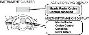
• If the vehicle continues to be driven without following the shift up/shift down request, the body control module (BCM) will automatically cancel the MRCC system to reduce the load on the engine.am3zzn00009189
-
Note
-
• When driving on a steep downhill, a shift down request may be indicated to decrease the load on the brakes required to maintain a constant vehicle speed.
*:Sophisticated Airbag Sensor control module