ENGINE CONTROL SYSTEM [SKYACTIV-G (WITHOUT CYLINDER DEACTIVATION (US))]
ENGINE CONTROL SYSTEM [SKYACTIV-G (WITHOUT CYLINDER DEACTIVATION (US))]
SM2565331
id0140u0139900
Outline
• L-jetronic *1 and D-jetronic *2 type detectors have been combined for intake air amount detection, improving the accuracy of the intake air amount measurement.
-
― MAF sensor adopted― MAP sensor adopted― IAT sensor No.1 and No.2 adopted
• Valve timing control has been adopted on both sides of the intake and exhaust, improving fuel economy and emission performance.
-
Intake side: Electric variable valve timing control
-
― Intake CMP sensor adopted― Electric variable valve timing motor/driver adopted― Electric variable valve timing relay adopted
-
Exhaust side: Hydraulic variable valve timing control
-
― Exhaust CMP sensor adopted
• Engine oil variable control has been adopted reducing engine load.
-
― Engine oil solenoid valve adopted
• The engine coolant control valve adjusts the engine coolant control valve opening angle and supplies engine coolant to the appropriate engine coolant passage according to the changes in the engine coolant temperature.
• Further engine warming has been promoted by blocking each water passage while the engine is cool.
-
― Coolant control valve adopted
• With the adoption of fuel pump control, fuel pump power consumption has been reduced, improving fuel economy.
-
― Fuel pump control module adopted
*1 :Measures the intake air amount directly using the MAF sensor.
*2 :Measures the intake air pressure introduced into the cylinder using the MAP sensor and calculates the intake air amount indirectly.
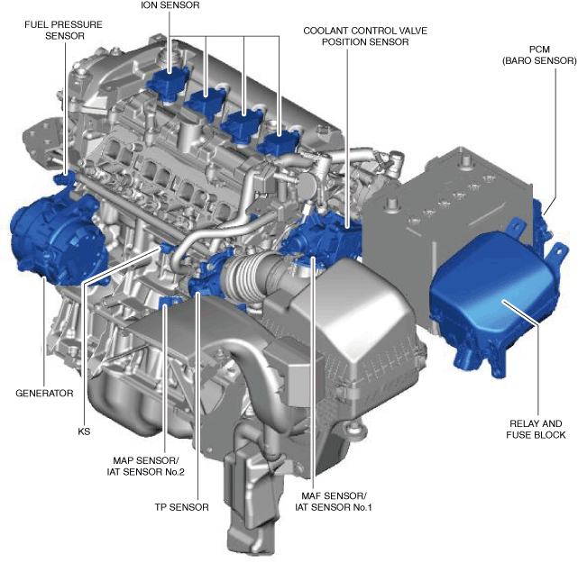
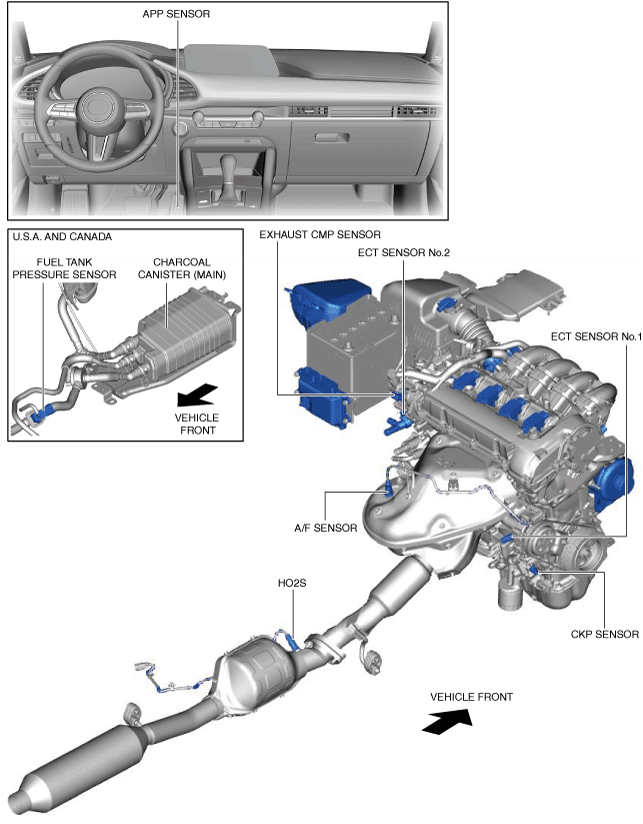
Structural View
Input device
atsuzn00000534
|
atsuzn00000573
|
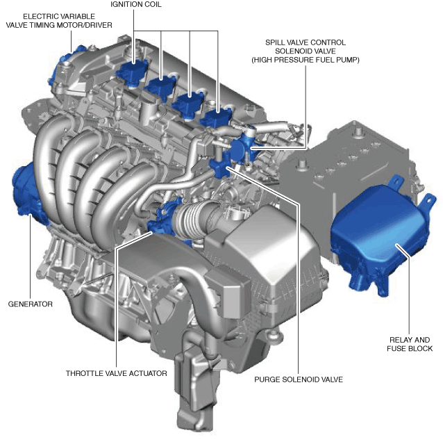
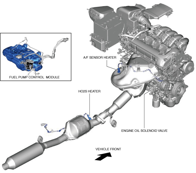
Output device
atsuzn00000536
|
am3zzn00007788
|
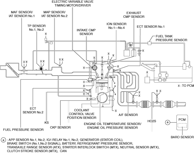
System Diagram
Input device
U.S.A. and CANADA
am3zzn00009088
|
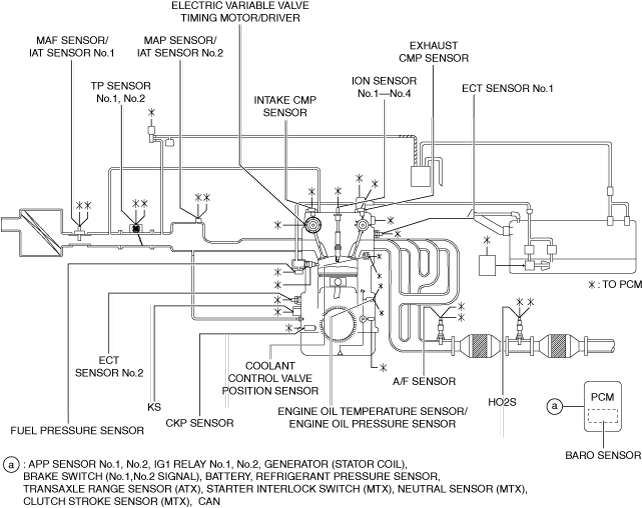
Except U.S.A. and CANADA
am3zzn00009089
|
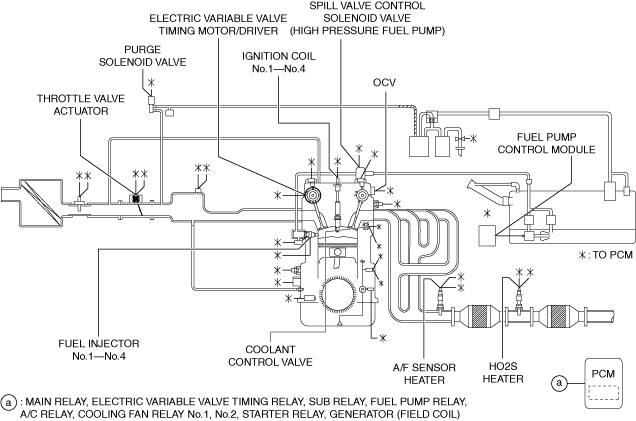
Output device
U.S.A. and CANADA
am3zzn00009090
|
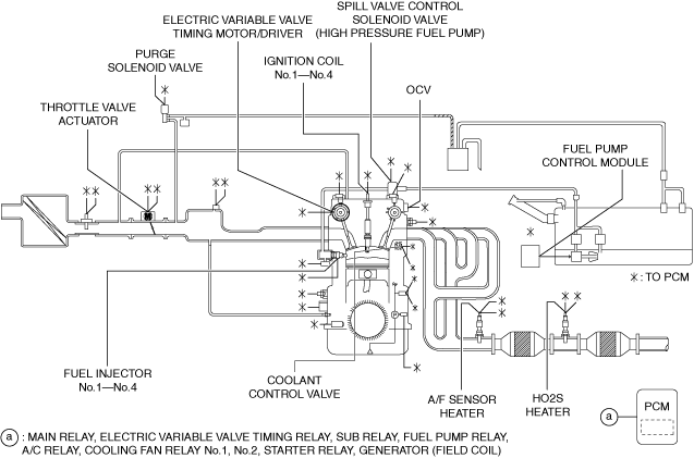
Except U.S.A. and CANADA
am3zzn00009091
|
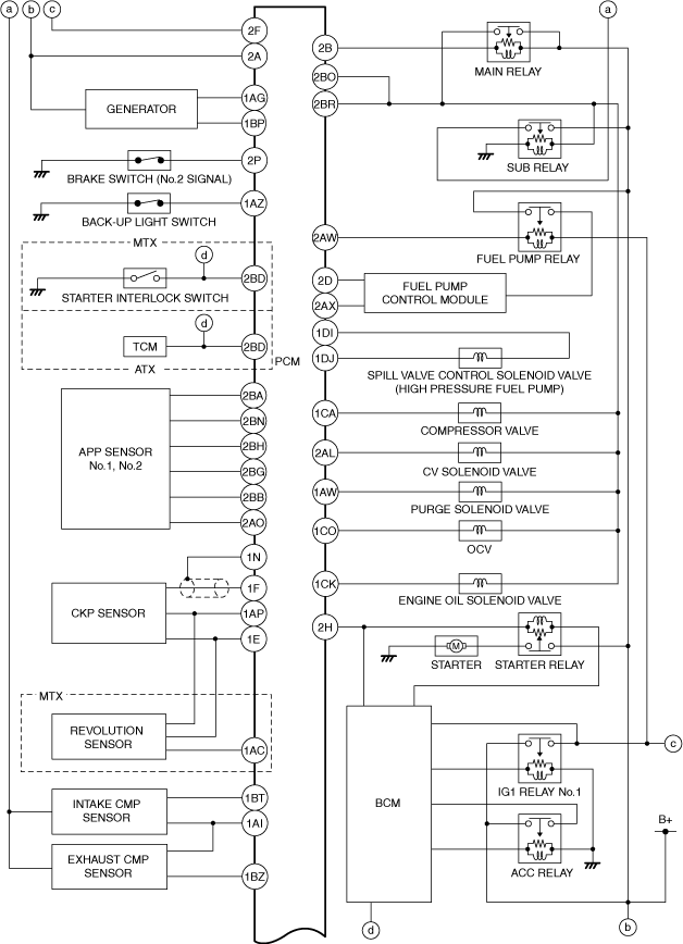
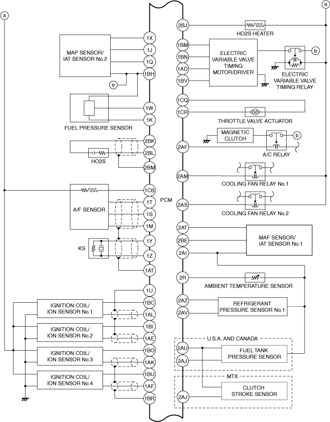
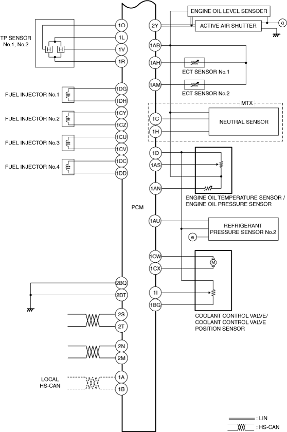
System Wiring Diagram
am3zzn00007785
|
am3zzn00009413
|
am3zzn00009175
|
Block Diagram
am3zzn00008274
|
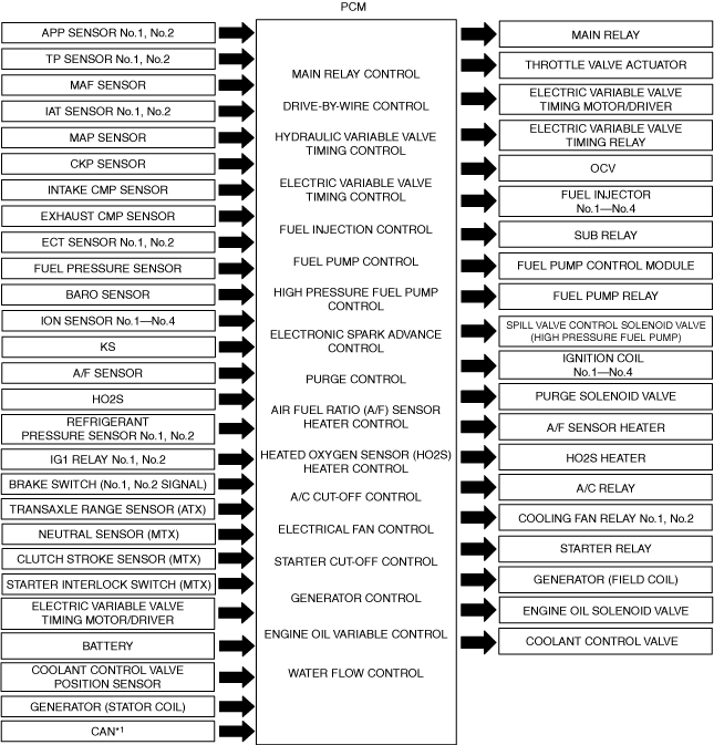
*1 :TCM (ATX), DSC HU/CM, BCM, ESU, instrument cluster, EPS control module
Relation Chart
• Each control system and their related input and output parts are as follows.
×: Applicable
|
Item |
MAIN RELAY CONTROL |
DRIVE-BY-WIRE CONTROL |
HYDRAULIC VARIABLE VALVE TIMING CONTROL |
ELECTRIC VARIABLE VALVE TIMING CONTROL |
FUEL INJECTION CONTROL SYSTEM |
FUEL PUMP CONTROL |
HIGH PRESSURE FUEL PUMP CONTROL |
ELECTRONIC SPARK ADVANCE CONTROL |
PURGE CONTROL |
AIR FUEL RATIO (A/F) SENSOR HEATER CONTROL |
HEATED OXYGEN SENSOR (HO2S) HEATER CONTROL |
A/C CUT-OFF CONTROL |
ELECTRICAL FAN CONTROL |
STARTER CUT-OFF CONTROL |
GENERATOR CONTROL |
ENGINE OIL VARIABLE CONTROL |
WATER FLOW CONTROL |
|---|---|---|---|---|---|---|---|---|---|---|---|---|---|---|---|---|---|
|
Input device
|
|||||||||||||||||
|
APP sensor No.1, No.2
|
×
|
×
|
×
|
×
|
×
|
×
|
×
|
||||||||||
|
TP sensor No.1, No.2
|
×
|
×
|
×
|
||||||||||||||
|
MAF sensor
|
×
|
×
|
×
|
×
|
×
|
×
|
×
|
×
|
×
|
||||||||
|
IAT sensor No.1
|
×
|
×
|
×
|
×
|
×
|
×
|
×
|
||||||||||
|
IAT sensor No.2
|
×
|
×
|
×
|
×
|
|||||||||||||
|
MAP sensor
|
×
|
×
|
×
|
×
|
×
|
×
|
|||||||||||
|
CKP sensor
|
×
|
×
|
×
|
×
|
×
|
×
|
×
|
×
|
×
|
×
|
×
|
×
|
×
|
×
|
|||
|
Intake CMP sensor
|
×
|
×
|
×
|
×
|
|||||||||||||
|
Exhaust CMP sensor
|
×
|
×
|
×
|
×
|
×
|
||||||||||||
|
ECT sensor No.1, No.2
|
×
|
×
|
×
|
×
|
×
|
×
|
×
|
×
|
×
|
×
|
|||||||
|
Fuel pressure sensor
|
×
|
×
|
×
|
×
|
|||||||||||||
|
BARO sensor
|
×
|
×
|
×
|
×
|
×
|
||||||||||||
|
Engine oil temperature sensor
|
×
|
×
|
×
|
×
|
|||||||||||||
|
Coolant control valve position sensor
|
×
|
||||||||||||||||
|
Ion sensor No.1—No.4
|
×
|
×
|
|||||||||||||||
|
KS
|
×
|
||||||||||||||||
|
A/F sensor
|
×
|
×
|
|||||||||||||||
|
HO2S
|
×
|
||||||||||||||||
|
Refrigerant pressure sensor No.1, No.2
|
×
|
×
|
|||||||||||||||
|
IG1 relay No.1, No.2
|
×
|
×
|
×
|
×
|
×
|
×
|
×
|
×
|
×
|
||||||||
|
Brake switch (No.1, No.2 signal)
|
×
|
||||||||||||||||
|
Transaxle range sensor (ATX)
|
×
|
×
|
×
|
||||||||||||||
|
Neutral sensor (MTX)
|
×
|
×
|
×
|
||||||||||||||
|
Clutch stroke sensor (MTX)
|
×
|
×
|
×
|
||||||||||||||
|
Starter interlock switch (MTX)
|
×
|
||||||||||||||||
|
Electric variable valve timing motor/driver
|
×
|
||||||||||||||||
|
Battery
|
×
|
×
|
×
|
×
|
×
|
×
|
×
|
||||||||||
|
Generator (Stator coil)
|
×
|
||||||||||||||||
|
CAN *1
|
×
|
×
|
×
|
×
|
×
|
×
|
×
|
×
|
×
|
||||||||
|
Output device
|
|||||||||||||||||
|
Main relay
|
×
|
||||||||||||||||
|
Throttle valve actuator
|
×
|
||||||||||||||||
|
Electric variable valve timing motor/driver
|
×
|
×
|
|||||||||||||||
|
Electric variable valve timing relay
|
×
|
||||||||||||||||
|
OCV
|
×
|
||||||||||||||||
|
Fuel injector No.1—No.4
|
×
|
||||||||||||||||
|
Sub relay
|
×
|
||||||||||||||||
|
Fuel pump control module
|
×
|
||||||||||||||||
|
Fuel pump relay
|
×
|
||||||||||||||||
|
Spill valve control solenoid valve (High pressure fuel pump)
|
×
|
||||||||||||||||
|
Ignition coil No.1—No.4
|
×
|
||||||||||||||||
|
Purge solenoid valve
|
×
|
||||||||||||||||
|
A/F sensor heater
|
×
|
||||||||||||||||
|
HO2S heater
|
×
|
||||||||||||||||
|
A/C relay
|
×
|
||||||||||||||||
|
Cooling fan relay No.1, No.2
|
×
|
||||||||||||||||
|
Starter relay
|
×
|
||||||||||||||||
|
Generator (Field coil)
|
×
|
||||||||||||||||
|
Spark plug
|
|||||||||||||||||
|
Oil pump
|
|||||||||||||||||
|
Engine oil solenoid valve
|
×
|
||||||||||||||||
|
Coolant control valve
|
×
|
||||||||||||||||
*1 :TCM (ATX), DSC HU/CM, BCM, ESU, instrument cluster, EPS control module