CRUISE CONTROL SYSTEM [SKYACTIV-G (WITHOUT CYLINDER DEACTIVATION (US))]
CRUISE CONTROL SYSTEM [SKYACTIV-G (WITHOUT CYLINDER DEACTIVATION (US))]
SM2565305
id0120u0903400
Cruise Control System
Outline
-
• By setting the vehicle speed using the cruise control switch, the cruise control system enables driving at a constant speed without having to operate the accelerator pedal.• The cruise control system reduces driver fatigue during long drives on expressways.
Function
-
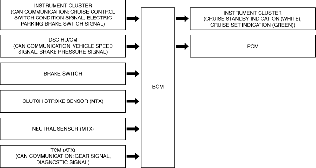
• The cruise control system performs engine control via the PCM to maintain the set vehicle speed based on the target acceleration speed signal from the BCM.• The relations between each component part and functions are as follows.
|
Component parts |
Functions |
||
|---|---|---|---|
|
BCM
|
The BCM has the following functions.
• Recognizes the set vehicle speed set by the driver based on the cruise control switch operation signal sent from the instrument cluster.
• Sends the set vehicle speed and the system status display request signals to the instrument cluster based on the recognized set vehicle speed.
• Sends the target acceleration speed signal to the PCM based on the recognized set vehicle speed.
|
||
|
Instrument cluster
|
CAN communication: cruise control switch condition signal
|
Cruise switch
|
The cruise control system main switch.
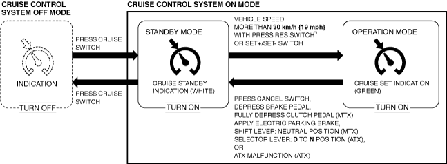
Cruise control system stopped
• By operating the switch, the cruise control system goes on standby.
Cruise control system standby
• By operating the switch, the cruise control system turns off.
|
|
CANCEL switch
|
The cruise control system cancel switch. While the cruise control system is operating, it goes on standby operating the switch.
|
||
|
RES switch
|
By operating the switch while the cruise control system is on standby and the vehicle is driven normally at more than 30 km/h {19 mph}, the PCM performs engine control so that the vehicle speed reaches the set vehicle speed stored in the BCM. (Operates when the BCM stores the previously set vehicle speed.)
|
||
|
SET+ switch
SET- switch
|
Cruise control system operating
• By operating the switch while the vehicle is driven normally at more than 30 km/h {19 mph}, the vehicle speed at the time the switch is pressed is stored in the BCM as the set vehicle speed, and the PCM performs engine control so that the vehicle speed reaches the set vehicle speed.
• Acceleration is controlled by pressing the SET+ switch or continuously pressing it.
• Deceleration is controlled by pressing the SET- switch or continuously pressing it.
|
||
|
CAN communication: electric parking brake switch signal
|
When the electric parking brake is applied, the cruise control system goes on standby. (The pre-set vehicle speed is stored.)
|
||
|
Cruise standby indication (white)
|
|||
|
Cruise set indication (green)
|
|||
|
DSC HU/CM
|
CAN communication: vehicle speed signal
|
The DSC HU/CM sends the vehicle speed signal to the BCM.
|
|
|
CAN communication: brake pressure signal
|
If the brake pressure exceeds 1.0 MPa {10 kgf/cm2, 145 psi}, the cruise control system goes on standby. (The pre-set vehicle speed is stored.)
|
||
|
Brake switch
|
When the brake pedal is pressed during cruise control, the cruise control system goes on standby. (The pre-set vehicle speed is stored.)
|
||
|
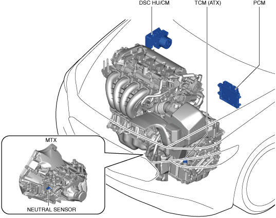
Clutch stroke sensor (MTX)
|
When the clutch pedal is pressed during cruise control, the cruise control system goes on standby. (The pre-set vehicle speed is stored.)
|
||
|
Neutral sensor (MTX)
|
When the shift lever is shifted to the neutral position during cruise control, the cruise control system goes on standby. (The pre-set vehicle speed is stored.)
|
||
|
TCM (ATX)
|
CAN communication: gear signal
|
• When the selector lever is shifted from D to N position during cruise control, the cruise control system goes on standby. (The pre-set vehicle speed is stored.)
• The cruise control system does not operate when the selector lever is in the N or P position.
• The cruise control system does not go on standby during cruise control even if the selector lever is shifted from the D to M position.
|
|
|
CAN communication: diagnostic signal
|
If there is a malfunction with the ATX, the cruise control system goes on standby. (The pre-set vehicle speed is stored.)
|
||
|
PCM
|
The PCM performs engine control to maintain the set vehicle speed based on the target acceleration speed signal from the BCM.
|
||
Structure/construction
-
System structure
-
 atsuzn00000585am3zzn00008270atsuzn00000587
-
Block Diagram
-
am3zzn00008271
Operation
-
• When the following conditions are met, the cruise control system goes on operation standby.
-
― Cruise switch is on― Brake pedal is not depressed― Clutch pedal is not depressed (MTX)― DSC is not operating― Smart brake support (SBS) is not operating― Electric parking brake is released― All doors are closed― Driver’s seat belt is fastened― No malfunction in DSC system (No DTCs stored in memory)― No malfunction in cruise control system (No DTCs stored in memory)― No malfunction in PCM system (No DTCs stored in memory)
-
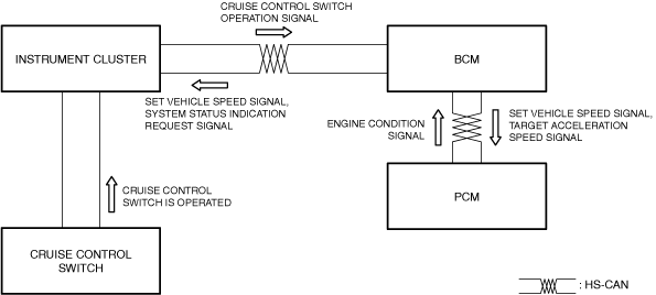
1.When the cruise control switch is operated, the BCM recognizes the set vehicle speed that was set by the driver based on the cruise control switch operation signal sent from the instrument cluster.
2.The BCM sends the set vehicle speed signal and a system status indication request signal to the instrument cluster based on the recognized set vehicle speed.
3.The BCM sends the target acceleration speed signal to the PCM based on the recognized set vehicle speed.
4.The PCM performs engine control to maintain the set vehicle speed based on the target acceleration speed signal from the BCM.
5.The instrument cluster displays the system operation screen based on the set vehicle speed signal and system status indication request signal from the BCM.
-
• If the vehicle speed decreases to 20 km/h {12 mph} or below while in constant speed control mode, the BCM switches to standby status.
am3zzn00008683
|
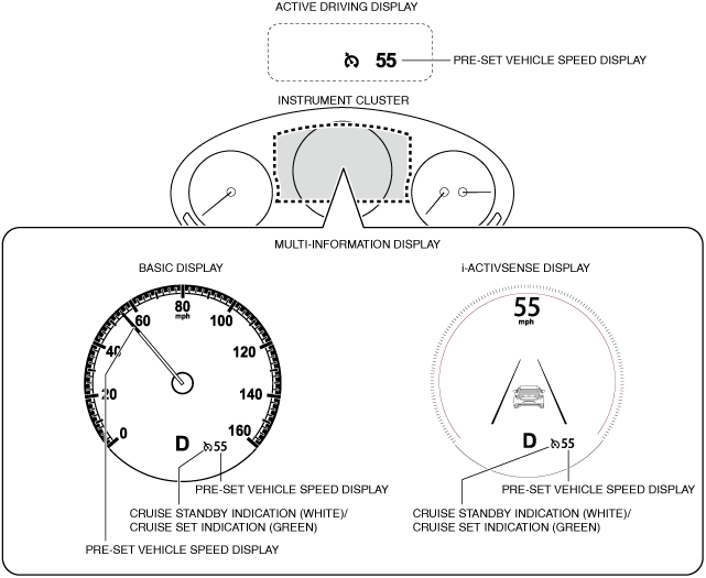
Cruise Standby Indication (White), Cruise Set Indication (Green)
Purpose
-
Cruise standby indication (white)
-
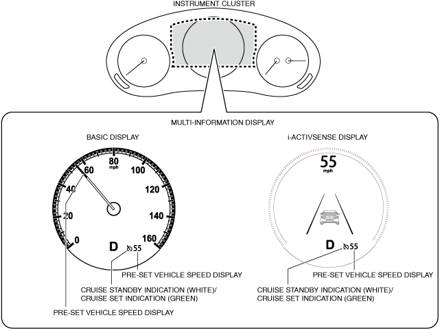
• The cruise standby indication (white) is displayed on the multi-information display in the instrument cluster while the cruise control system is on standby to inform the driver that the cruise control system is on standby.
-
Cruise set indication (green)
-
• The cruise set indication (green) is displayed on the instrument cluster multi-information display while the cruise control system is operating to inform the driver that the cruise control system is operating.
Function
-
• The display conditions of the cruise standby indication (white) and cruise control indication (green) are as follows.am3zzn00009293
Construction
-
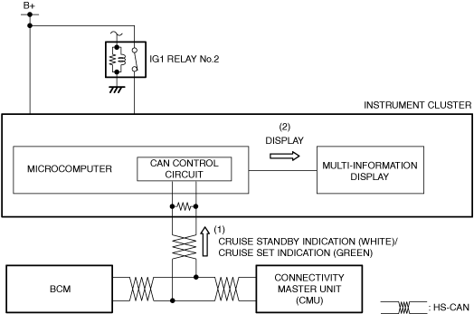
• The cruise standby indication (white) and cruise control indication (green) are displayed on the multi-information display.atsuzn00000591
Operation
1.The instrument cluster receives (1) a cruise standby indication (white) illumination request signal or cruise control indication (green) illumination request signal from the BCM via CAN communication.
2.The instrument cluster displays (2) the cruise standby indication (white) or the cruise standby indication (green) on the multi-information display based on the cruise standby indication (white) illumination request signal or the cruise standby indication (green) illumination request signal.
atsuzn00000592
|