360°VIEW MONITOR SYSTEM
360°VIEW MONITOR SYSTEM
SM2334320
id151000004300
Outline
am3zzn00008671
|
am6xun00004249
|
-
― When entering T-intersections― When making left/right turns― When accelerating vehicle after parking or stopping vehicle― When vehicles pass each other on narrow lane roads― When parallel parking― When reversing
Functions
Top view
-
• The top view assists the driver in checking the area around the vehicle while the vehicle is moving forward or reversing, and combines video signals from the four cameras (front camera, side cameras (LH, RH), rear mount camera) equipped to the vehicle and displays the viewpoint of the area around the vehicle from the top of the vehicle on the center display.• The top view displays on the right side of the screen when the screen of the front view, front wide view, rear view or rear wide view is being displayed.
 am3zzn00007337
Front view
-
• The front view assists the driver in checking the vehicle front while the vehicle is moving forward, and displays images shot by the front camera equipped to the vehicle on the center display.• The front view displays on the left side of the screen when the screen of the top view is being displayed.am3zzn00007338
Front wide view
-
• The front wide view assists the driver in checking the vehicle front and the sides of the vehicle while the vehicle is moving forward, and displays images shot by the front camera equipped to the vehicle on the center display.• The front wide view displays wide angle images from the front view on the left side of the screen.am3zzn00007339
Side view
-
• The side view assists the driver in checking the left/right/front side of the vehicle while the vehicle is moving forward, and displays images shot by the two cameras (side cameras (LH, RH)) equipped to the vehicle on the center display.am3zzn00007340
Rear view
-
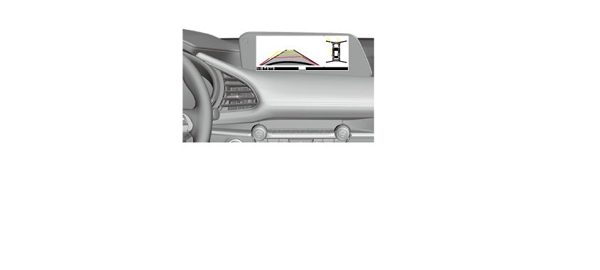
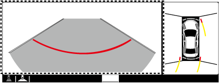
• The rear view assists the driver in checking the vehicle rear while the vehicle is reversing, and displays images shot by the rear mount camera equipped to the vehicle on the center display.• The rear view displays on the left side of the screen when the screen of the top view is being displayed.am3zzn00007342
Rear wide view
-
• The rear wide view assists the driver in checking the sides of the vehicle and the vehicle rear while the vehicle is reversing, and displays images shot by the rear mount camera equipped to the vehicle on the center display.• The rear wide view displays wide angle images from the rear view on the center display.am3zzn00007341
Indication function
-
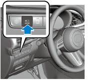
• Images are displayed on the screen when the 360° view monitor switch is pressed or the selector lever is in R position (ATX)/the shift lever is in reverse position (MTX) with all of the following conditions met.
-
― Ignition is switched ON (engine off or on)
-
am3zzn00007343
|
Screen display switching function
-
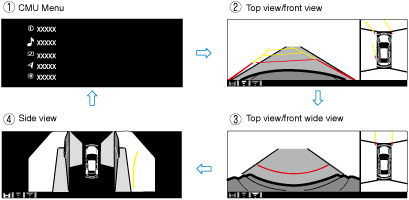
• When the 360° view monitor switch is pressed while the top view/front view, top view/rear view, top view/front wide view, top view/rear wide view, or side view is displayed, the 360° view monitor control module switches the displayed image.
When top view/front view, top view/front wide view, side view is displayed
am3zzn00008181
|
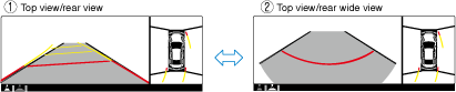
When top view/rear view, top view/rear wide view is displayed
am3zzn00008182
|
Parking assist system
-
• The parking assist system uses ultrasonic sensors to detect obstructions around the vehicle, and notifies the driver of the approximate distance from the vehicle to the surrounding obstruction using sound and an obstruction detection indication. For details on the parking assist system, refer to the [PARKING SENSOR SYSTEM]. (See PARKING ASSIST SYSTEM.)
Malfunction indication function
-
• The 360° view monitor control module displays the system malfunction condition on the center display.
-
Note
-
• If each camera has a malfunction, the image taken from the applicable camera is displayed on the center display in black.
-
Personalization feature
-
• Refer to the [CENTER DISPLAY PERSONALIZATION FEATURES SETTING PROCEDURE] in the workshop manual for the detailed setting procedure.
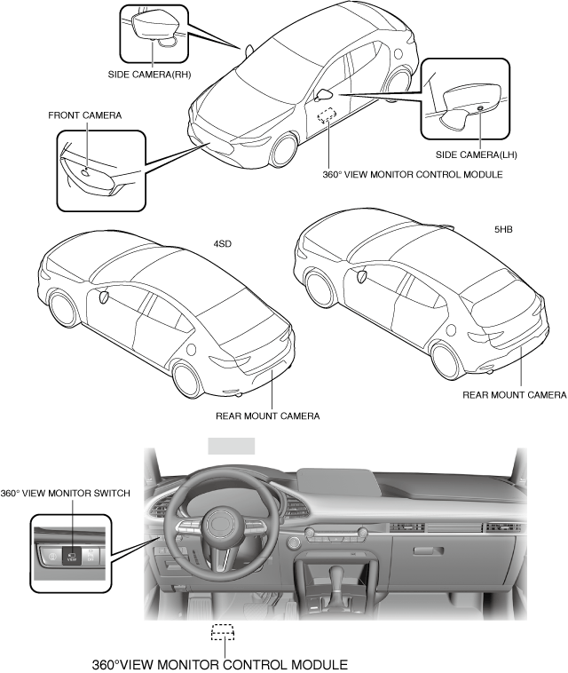
Structural View
-
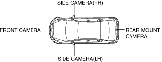
― 360°view monitor control module(See 360°VIEW MONITOR CONTROL MODULE.)― front camera(See 360°VIEW MONITOR SYSTEM CAMERA.)― side camera(RH)(See 360°VIEW MONITOR SYSTEM CAMERA.)― side camera(LH)(See 360°VIEW MONITOR SYSTEM CAMERA.)― rear mount camera(See 360°VIEW MONITOR SYSTEM CAMERA.)― 360°view monitor switch(See 360°VIEW MONITOR SWITCH.)
am3zzn00008183
|
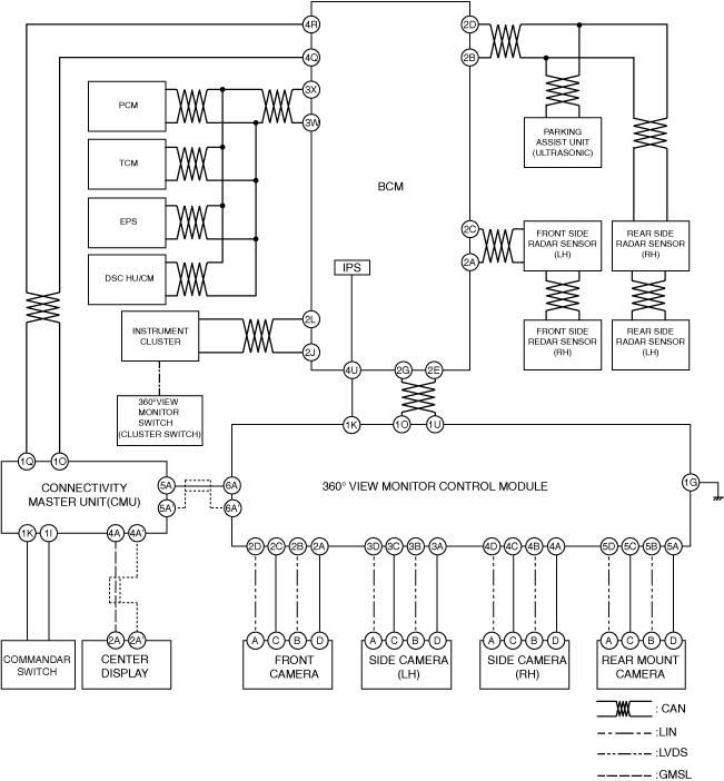
System diagram
am3zzn00008184
|
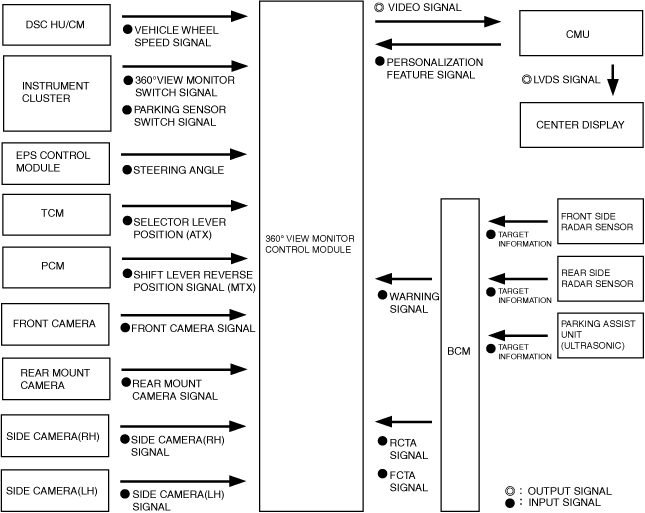
Block Diagram
am3zzn00008185
|
Screen Display
Icon display
-
• The icons displayed on the screen are as follows.
Display example
am3zzn00007346
|
|
Display/Icon
|
Content
|
|
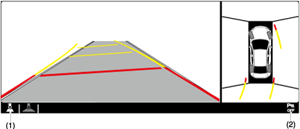
(1)View status icon
|
Indicates which image is displayed among the front view, front wide view, side view, rear view, and rear wide view.
|
|
(2)Parking sensor status icon
|
Indicates that the parking sensor has a problem or the parking sensor system is switched off.
|
Top view/front view shooting range
-
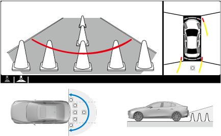
• The top view/front view displays the shooting range shown in the figure.
-
Note
-
• For the top view display, the diagonal lines at the front and rear of the vehicle image and the seams where each of the camera images merge are blind spots.• Because images displayed in the top view screen are processed from each camera, the top view display may be displayed in the following ways.
-
― If an image containing an object with a color is picked up in the wide range by any of the cameras, it may display in that color.― Color may appear differently that in actuality at the seams where each of the camera images merge.― Obstructions displayed in the front view may not display on the top view screen.― If the position or angle of each camera changes due to tilting of the vehicle, the image may appear distorted.― Lines on the road may appear distorted at the seams where each of the camera images merge.― People or obstructions displayed on the screen may appear differently than in actuality. (People or obstructions may appear fallen, larger, or longer than they actually are.)
-
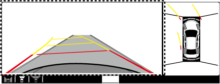
Top view/front view shooting range
am3zzn00007477
|
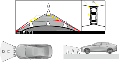
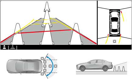
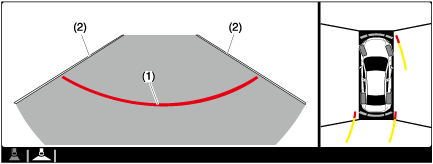
Top view/front view indication
am3zzn00007348
|
|
Display item |
Display line color |
Function |
|---|---|---|
|
(1)TIRE ICON
|
—
|
Icon indicating tire direction
|
|
(2)PROJECTED VEHICLE PATH LINES (STEERING INTERLOCKING)
|
Yellow & Red
|
Projected vehicle path calculated from steering angle
• Line indicating the path where the edge of the front bumper is expected to travel.
• Line indicating the path where the inner side of the vehicle is expected to travel.
|
|
(3)VEHICLE WIDTH EXTENSION LINES (FIXED)
|
Blue
|
Vehicle width extension line with including the power outer mirror.
|
|
(4)Projected vehicle path distance guide lines (steering interlocking)
|
Red
|
Distance guide line indicating approx. 0.5 m {19 in} from front end of front bumper
|
|
Yellow
|
Distance guide line indicating approx.1.0 m {39 in} and 2.0 m {78 in} from front end of front bumper
|
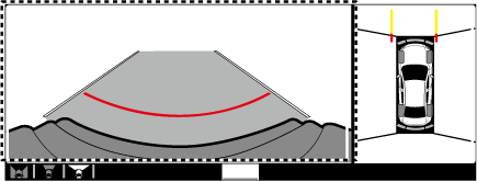
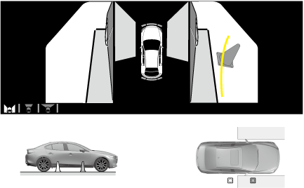
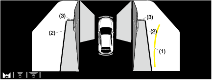
Top view/front wide view
-
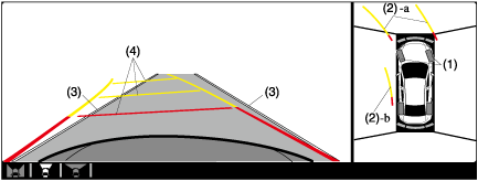
• The top view/front wide view shoots the range shown in the figure.
Top view/front wide view shooting range
am3zzn00007478
|
Top view/front wide view display
am3zzn00008672
|
|
Display item |
Display line color |
Function |
|---|---|---|
|
(1)DISTANCE GUIDE LINES
|
Red
|
Distance guide line indicating approx. 0.5 m {19 in} from front end of front bumper
|
|
(2)VEHICLE WIDTH EXTENSION LINES
|
Blue
|
Vehicle width extension line with including the power outer mirror
|
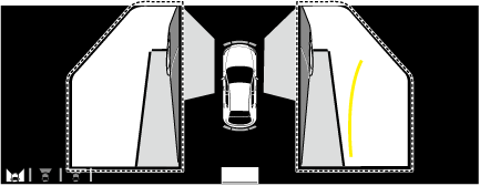
Side view
-
• The side view shoots the range shown in the figure.
Side view shooting range
am3zzn00007479
|
Side view display
am3zzn00007351
|
|
Display item |
Display line color |
Function |
|---|---|---|
|
(1)PROJECTED VEHICLE PATH LINES
|
Yellow
|
Projected vehicle path calculated from steering angle
|
|
(2)VEHICLE PARALLEL GUIDE LINES
|
Blue
|
Line indicating the approximate vehicle width including the power outer mirror.
|
|
(3)VEHICLE FRONT END GUIDE LINES
|
Blue
|
Distance guide line from front end of front bumper
|
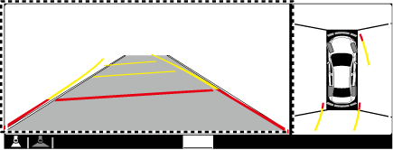
Top view/rear view
-
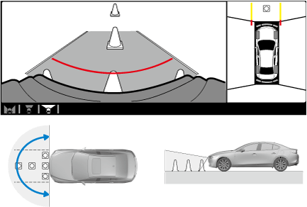
• The top view/rear view shoots the range shown in the figure.
-
Note
-
• For the top view display, the diagonal lines at the front and rear of the vehicle image and the seams where each of the camera images merge are blind spots.• Because images displayed in the top view screen are processed from each camera, the top view display may be displayed in the following ways.
-
― If an image containing an object with a color is picked up in the wide range by any of the cameras, it may display in that color.― Color may appear differently that in actuality at the seams where each of the camera images merge.― Obstructions displayed in the front view may not display on the top view screen.― If the position or angle of each camera changes due to tilting of the vehicle, the image may appear distorted.― Lines on the road may appear distorted at the seams where each of the camera images merge.― People or obstructions displayed on the screen may appear differently than in actuality. (People or obstructions may appear fallen, larger, or longer than they actually are.)
-
Top view/rear view shooting range
am3zzn00007480
|
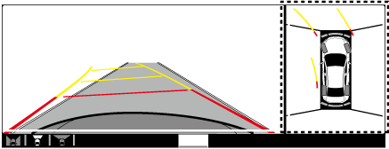
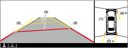
Top view/rear view display
am3zzn00007353
|
|
Display item |
Display line color |
Function |
|---|---|---|
|
(1)TIRE ICON
|
—
|
Icon indicating tire direction
|
|
(2)PROJECTED VEHICLE PATH LINES (STEERING INTERLOCKING)
|
Yellow
|
Projected vehicle path calculated from steering angle
• Line indicating the path where the rear tire is expected to travel.
• Line indicating the path where the outer side of the vehicle is expected to travel.
|
|
(3)VEHICLE WIDTH EXTENSION LINES (FIXED)
|
Blue
|
Vehicle width extension line with including the power outer mirror
|
|
(4)Projected vehicle path distance guide lines (steering interlocking)
|
Red
|
Distance guide line indicating approx. 0.5 m {19 in} from rear end of rear bumper
|
|
Yellow
|
Distance guide line indicating approx. 1.0 m {39 in} and 2.0 m {78 in} from rear end of rear bumper
|
Top view/rear wide view
-
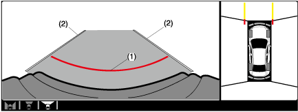
• The top view/rear wide view shoots the range shown in the figure.
am3zzn00007481
|
Top view/rear wide view display
am3zzn00008673
|
|
Display item |
Display line color |
Function |
|---|---|---|
|
(1)DISTANCE GUIDE LINES
|
Red
|
Distance guide line indicating approx. 0.5 m {19 in} from front end of front bumper
|
|
(2)VEHICLE WIDTH EXTENSION LINES
|
Blue
|
Vehicle width extension line with including the power outer mirror
|
Operation
Top view/front view, top view/front wide view, side view display operation
-
Operation condition
-
• When all of the following conditions are met, the top view/front view, top view/front wide view, side view can be displayed.
-
― Ignition is switched ON (engine off or on)― Selector lever is in a position other than R (ATX)― Shift lever is in a position other than reverse or neutral (MTX)
-
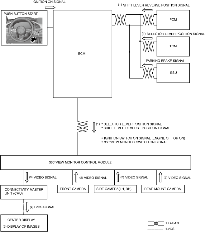
1.When a 360° view monitor switch ON signal (1) is received with the operation conditions met, the 360° view monitor control module receives an image signal (2) from the front camera/side cameras (LH, RH)/rear mount camera.
2.The received image signal processes an image, and then the 360° view monitor control module sends (3) it to the CMU.
3.The CMU converts the received video signal to a LVDS signal and sends (4) the LVDS signal to the center display.
4.The center display indicates (5) the images at the area around the vehicle based on the LVDS signal received from the CMU.
5.When any of the following conditions is met, the 360° view monitor control module switches the images indicated on the center display to not display.
-
• Parking brake ON signal is received (parking brake is applied) (MTX)• Selector lever is shifted to P position (ATX)• When 360° view monitor switch is pressed while vehicle speed is less than approx. 15 km/h {9.3 mph}
-
― Approx. 270 sec have elapsed since 360° view monitor switch was pressed― Vehicle speed is approx. 15 km/h {9.3 mph} or more
• When 360° view monitor switch is pressed while vehicle speed is approx. 15 km/h {9.3 mph} or more-
― Vehicle speed is approx. 15 km/h {9.3 mph} or more after approx. 8 sec have elapsed since 360° view monitor switch was pressed― 262 s have elapsed from the point when the vehicle speed was less than 15 km/h {9.3 mph} or the vehicle speed exceeds 15 km/h {9.3 mph} after 8 s have elapsed since pressing the 360° view monitor switch.
-
am3zzn00008186
|

Top view/rear view, top view/rear wide view display operation
-
Operation condition
-
• When all of the following conditions are met, the top view/rear view, top view/rear wide view can be displayed.
-
― Ignition is switched ON (engine off or on)― Selector lever is in R position(ATX)― Shift lever is in reverse position(MTX)
-
1.When a selector lever R position signal(ATX) or shift lever reverse position signal(MTX) is received (1) with the operation conditions met, the 360° view monitor control module receives an image signal (2) from the front camera/side cameras (LH, RH)/rear mount camera.
2.The received image signal processes an image, and then the 360° view monitor control module sends (3) it to the CMU.
3.The CMU converts the received video signal to a LVDS signal (4) and sends the LVDS signal to the center display.(4)
4.The center display indicates (5) the images at the area around the vehicle based on the LVDS signal received from the CMU.
5.When any of the following conditions is met, the 360° view monitor control module switches the images indicated on the center display to non-display.
-
• Parking brake ON signal is received (parking brake is applied)(MTX)• Selector lever is shifted to P position(ATX)
am3zzn00008187
|