MULTIPLEX COMMUNICATION SYSTEM [(US)]
MULTIPLEX COMMUNICATION SYSTEM [(US)]
SM2334308
id1000000014x1
Outline
• A control area network (CAN) system has been adopted in which the multiple control modules send/receive signals using two common communication lines.
ac5uun00002862
|
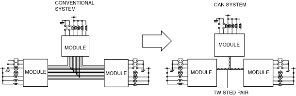
• Local CAN, ISO communication, or LIN communication has been adopted for the individual communication between control modules in consideration of the communication speed and the cost.
System Wiring Diagram
-
Note
-
• The following figure shows the CAN/LIN communication/ISO communication/local CAN connection conditions. The availability of the equipment may differ depending on the vehicle specifications.
CAN communication
am3zzn00009421
|
Local CAN
am3zzn00007934
|
LIN communication
am3zzn00009422
|
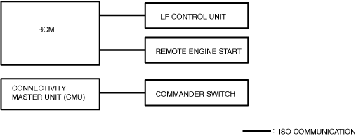
ISO communication
am3zzn00009423
|
Structural View
-
Note
-
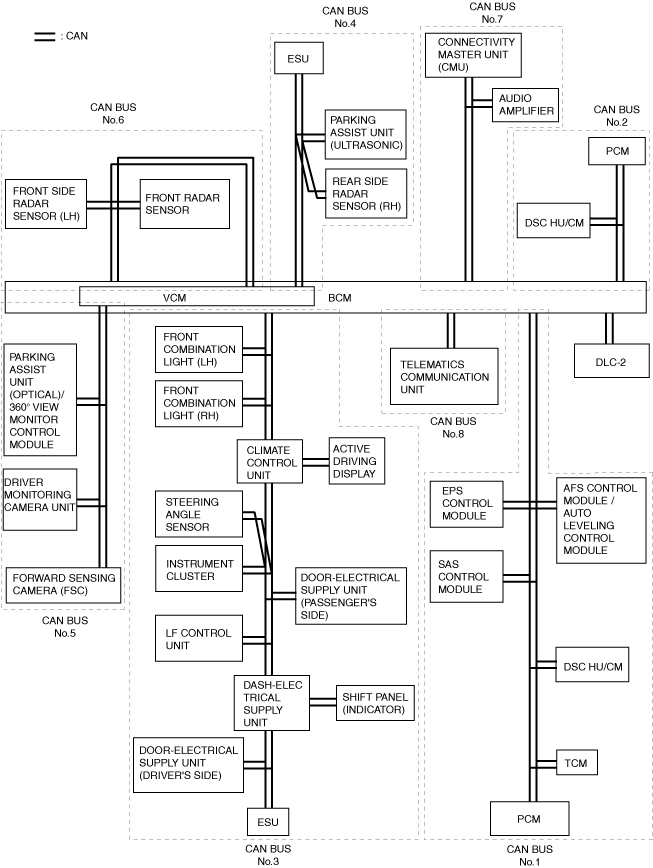
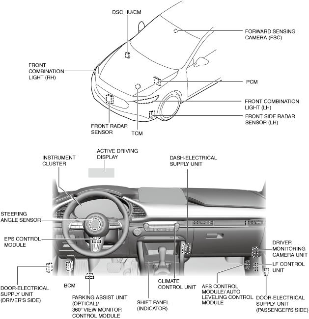
• The following figure shows the installation positions for the equipment which perform CAN communication. The availability of the equipment may differ depending on the vehicle specifications.
am3zzn00009424
|
am3zzn00009425
|
Function
CAN (controller area network) system
-
• CAN BUS No.1 is used for communication between the following modules:
-
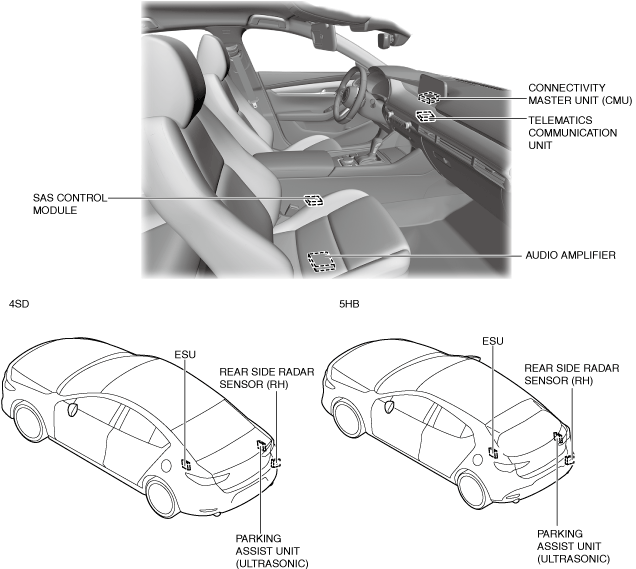
― BCM― EPS control module― Adaptive front lighting system (AFS) control module/auto leveling control module― SAS control module― DSC HU/CM― TCM― PCM
• CAN BUS No.2 is used for communication between the following modules:-
― BCM― DSC HU/CM― PCM
• CAN BUS No.3 is used for communication between the following modules:-
― BCM― Front combination light (LH)― Front combination light (RH)― Climate control unit― Active driving display― Steering angle sensor― Instrument cluster― Door-electrical supply unit (driver’s side)― Door-electrical supply unit (passenger’s side)― LF control unit― Dash-electrical supply unit― Shift panel (indicator)― Electrical supply unit (ESU)
• CAN BUS No.4 is used for communication between the following modules:-
― BCM― Rear side radar sensor (RH)― Parking assist unit (ultrasonic)― Electrical supply unit (ESU)
• CAN BUS No.5 is used for communication between the following modules:-
― BCM― Parking assist unit (optical)/360° view monitor control module― Driver monitoring camera unit― Forward sensing camera (FSC)
• CAN BUS No.6 is used for communication between the following modules:-
― BCM― Front side radar sensor (LH)― Front radar sensor
• CAN BUS No.7 is used for communication between the following modules:-
― BCM― Audio amplifier― Connectivity master unit (CMU)
• CAN BUS No.8 is used for communication between the following modules:-
― BCM― Telematics communication unit
-
Local CAN
-
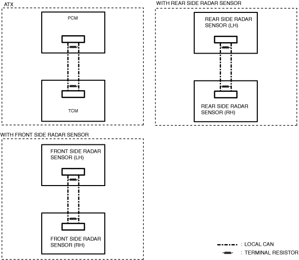
• Local CAN is used for communication between the following modules:
-
― Between PCM and TCM― Between front side radar sensor (LH) and front side radar sensor (RH)― Between rear side radar sensor (LH) and rear side radar sensor (RH)
-
LIN communication
-
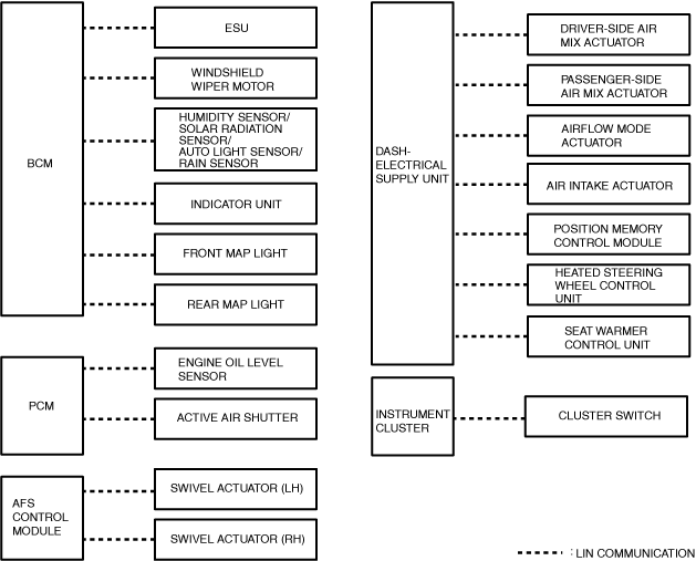
• LIN communication is used for communication between the following modules:
-
― Between BCM and electrical supply unit (ESU)― Between BCM and windshield wiper motor― Between BCM and humidity sensor/solar radiation sensor/auto light sensor/rain sensor― Between BCM and indicator unit― Between BCM and front map light― Between BCM and rear map light― Between dash-electrical supply unit and driver-side air mix actuator― Between dash-electrical supply unit and passenger-side air mix actuator― Between dash-electrical supply unit and airflow mode actuator― Between dash-electrical supply unit and air intake actuator― Between dash-electrical supply unit and heated steering wheel control unit― Between dash-electrical supply unit and position memory control module― Between dash-electrical supply unit and seat warmer control unit― Between PCM and engine oil level sensor― Between PCM and active air shutter― Between adaptive front lighting system (AFS) control module and swivel actuator (LH)― Between adaptive front lighting system (AFS) control module and swivel actuator (RH)― Between instrument cluster and cluster switch
-
ISO communication
-
• ISO communication is used for communication between the following modules:
-
― Between BCM and LF control unit― Between BCM and remote engine start― Between connectivity master unit (CMU) and commander switch
-
Construction
CAN
-
• The CAN BUS No.1 has terminal resistors built into the following units which form the CAN lines.
-
― BCM― PCM
• The CAN BUS No.2 has terminal resistors built into the following units which form the CAN lines.-
― BCM― PCM
• The CAN BUS No.3 has terminator resistors built into the following units which form the CAN lines.-
― BCM― Electrical supply unit (ESU)
• The CAN BUS No.4 has terminal resistors built into the following units which form the CAN lines.-
― BCM― Electrical supply unit (ESU)
• The CAN BUS No.5 has terminal resistors built into the following units which form the CAN lines.-
― BCM― Forward sensing camera (FSC)
• The CAN BUS No.6 has terminal resistors built into the following units which form the CAN lines.-
― BCM
• The CAN BUS No.7 has terminal resistors built into the following units which form the CAN lines.-
― BCM― Connectivity master unit (CMU)
• The CAN BUS No.8 has terminal resistors built into the following units which form the CAN lines.-
― BCM― Telematics communication unit
-
Local CAN
-
• The local CAN has terminator resistors built into the following units which form the CAN lines.
-
― PCM― TCM― Front side radar sensor (LH)― Front side radar sensor (RH)― Rear side radar sensor (LH)― Rear side radar sensor (RH)
-
LIN communication
-
• The LIN communication has drivers built into the following units which form the LIN communication lines.
-
― BCM― Electrical supply unit (ESU)― Windshield wiper motor― Humidity sensor/solar radiation sensor/auto light sensor/rain sensor― Indicator unit― Front map light― Rear map light― Dash-electrical supply unit― Driver-side air mix actuator― Passenger-side air mix actuator― Airflow mode actuator― Air intake actuator― Heated steering wheel control unit― Position memory control module― Seat warmer control unit― PCM― Engine oil level sensor― Active air shutter― Adaptive front lighting system (AFS) control module― Swivel actuator (LH)― Swivel actuator (RH)― Instrument cluster― Cluster switch
-
ISO communication
-
• The ISO communication has drivers built into the following units which form the ISO communication lines.
-
― BCM― LF control unit― Remote engine start― Connectivity master unit (CMU)― Commander switch
-