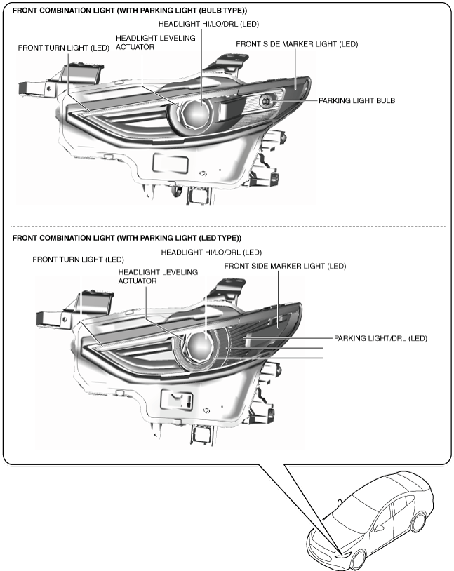
FRONT COMBINATION LIGHT
FRONT COMBINATION LIGHT
SM2334240
id091800010200
Purpose
Function
Structure/Construction
-
― Headlight HI/LO/daytime running light (DRL) (LED)― Front turn light (LED)― Front side marker light (LED)― Parking light/daytime running light (DRL) (LED) (with parking light (LED type))― Headlight leveling actuator― Swivel actuator (with adaptive front lighting system (AFS))
-
Note
-
• Fogging or condensation on the inside of the front combination lights may occur, however, it is a natural phenomenon occurring as a result of a temperature difference between the interior and exterior of the front combination lights and has no effect on the light performance.• Fogging or condensation occurring as a natural phenomenon will dissipate when the temperature inside the front combination lights rises after the headlights are illuminated and a period of time has elapsed.
am3zzn00007297
|
Operation
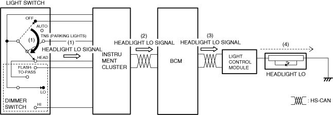
Headlight LO
1.When the light switch is in the HEAD position and the dimmer switch is in the LO position, the instrument cluster detects (1) a headlight LO signal.
2.The instrument cluster sends (2) the headlight LO signal to the body control module (BCM) via CAN communication.
3.When the body control module (BCM) receives the headlight LO signal with the ignition switched ON (engine off or on), it sends (3) a headlight LO on request signal to the light control module via CAN communication.
4.When the light control module receives the headlight LO on request signal, it turns the headlights LO on (4).
am3zzn00008696
|
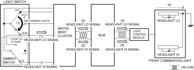
Headlight HI
1.When the light switch is in the HEAD position and the dimmer switch is in the HI position, the instrument cluster detects (1) a headlight LO signal and headlight HI signal.
2.The instrument cluster sends (2) the headlight LO signal and headlight HI signal to the body control module (BCM) via CAN communication.
3.When the body control module (BCM) receives the headlight LO signal and headlight HI signal with the ignition switched ON (engine off or on), it sends (3) a headlight LO on request signal and headlight HI on request signal to the light control module via CAN communication.
4.When the light control module receives the headlight LO on request signal and headlight HI on request signal, it turns the headlights LO and headlights HI on (4).
am3zzn00008697
|
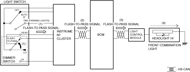
Flash-to-pass
1.When the dimmer switch is in the passing position, the instrument cluster detects (1) a passing signal.
2.The instrument cluster sends (2) the passing signal to the body control module (BCM) via CAN communication.
3.When the body control module (BCM) receives the passing signal with the ignition switched ON (engine off or on), it sends (3) a headlight LO on request signal and headlight HI on request signal to the light control module.
4.When the light control module receives the headlight LO on request signal and headlight HI on request signal, it turns the headlights LO and headlights HI on (4).
am3zzn00009330
|
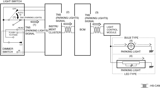
Parking light
1.When the light switch is in the TNS position, the instrument cluster detects (1) a TNS signal.
2.The instrument cluster sends (2) the TNS signal to the body control module (BCM) via CAN communication.
3.When the body control module (BCM) receives the TNS signal, it sends (3) a TNS on request signal to the light control module via CAN communication.
4.When the light control module receives the TNS on request signal, it turns the parking lights on (4).
am3zzn00008699
|
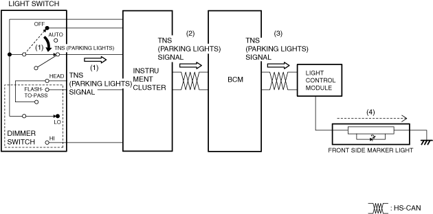
Front side marker light
1.When the light switch is moved to the TNS (parking lights) position, the instrument cluster detects (1) a TNS (parking lights) signal.
2.The instrument cluster sends (2) the TNS (parking lights) signal to the BCM via CAN communication.
3.When the BCM receives the TNS (parking lights) signal, it turns (3) the TNS relay on.
4.When the TNS relay turns on, the front side marker light is illuminated (4).
am3zzn00007284
|
Front turn light
-
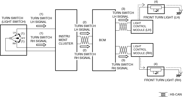
Turn light system
-
1. When the turn switch is in the LH or RH position, the instrument cluster detects (1) a turn switch LH signal or turn switch RH signal.2. The instrument cluster sends (2) the turn switch LH signal or turn switch RH signal to the body control module (BCM) via CAN communication.3. When the body control module (BCM) receives the turn switch LH signal or turn switch RH signal with the ignition switched ON (engine off or on), it sends (3) a turn switch LH on signal or turn switch RH on signal to the light control module via CAN communication.4. When the light control module receives the turn switch LH on signal or turn switch RH on signal, it flashes (4) the front turn light (LH) or front turn light (RH).
am3zzn00008700
|
-
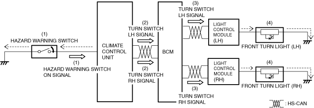
Hazard warning system
-
1. When the hazard warning switch turns on, the instrument cluster detects (1) a hazard warning switch on signal.2. The instrument cluster sends (2) the hazard warning switch on signal to the body control module (BCM) via CAN communication as a turn switch LH signal and turn switch RH signal.3. When the body control module (BCM) receives the turn switch LH signal and turn switch RH signal, it sends (3) a turn switch LH flash request signal and turn switch RH flash request signal to the light control module via CAN communication.4. When the light control module receives the turn switch LH flash request signal and turn switch RH flash request signal, it flashes (4) the front turn light (LH) and front turn light (RH).
am3zzn00008701
|
Headlight leveling actuator
-
• Refer to the [HEADLIGHT LEVELING ACTUATOR]. (See HEADLIGHT LEVELING ACTUATOR.)
Daytime running light (DRL) system
-
• Refer to the [DAYTIME RUNNING LIGHT (DRL) SYSTEM]. (See DAYTIME RUNNING LIGHT (DRL) SYSTEM.)
Swivel actuator (with adaptive front lighting system (AFS))
-
• Refer to the [SWIVEL ACTUATOR]. (See SWIVEL ACTUATOR.)