ELECTRIC POWER STEERING SYSTEM [(US)]
ELECTRIC POWER STEERING SYSTEM [(US)]
SM2334129
id0613002459x1
Outline
Specifications
|
Item |
Specification |
|||
|---|---|---|---|---|
|
Steering wheel
|
Outer diameter
|
(mm {IN})
|
372 {14.6}
|
|
|
Lock to lock
|
(turns)
|
2.90
|
||
|
Steering column and shaft
|
Shaft type
|
Collapsible
|
||
|
Joint type
|
Cross-shaped joint
|
|||
|
Tilt amount
|
(mm {IN})
|
45 {1.8}
|
||
|
Telescope amount
|
(mm {IN})
|
70 {2.8}
|
||
|
Steering gear and linkage
|
Type
|
Rack-and-pinion
|
||
|
Rack stroke
|
(mm {IN})
|
154.4 {6.079}
|
||
|
Power steering system
|
Power assist type
|
Electric motor assist (Column assist type)
|
||
Purpose, Function
Construction
-
― Manual steering mechanism Consists of the steering wheel, steering column, intermediate shaft, and steering gear and linkage.― Electric assist mechanism Consists of the EPS motor and reduction gear.― Control mechanism Consists of the EPS CM and torque sensor.
-
• The EPS CM communicates with the PCM, DSC HU/CM, SAS control module, instrument cluster, and CMU via CAN communication.
-
|
Part name |
Functions |
|---|---|
|
EPS CM
|
• Calculates the optimum assist force based on the signals from the torque sensor, EPS motor, PCM, DSC HU/CM, and SAS control module, and outputs the EPS motor drive current.
• After the vehicle begins moving, the system performs self-learning of the steering angle neutral position based on the signals from the DSC HU/CM and the SAS control module, and outputs it as a steering angle (estimated absolute steering angle) signal to CAN.
• Outputs a power steering malfunction indication on request signal signal to CAN when there is a malfunction in the EPS system.
|
|
PCM
|
• Transmits an engine speed signal to the EPS CM via CAN communication.
|
|
DSC HU/CM
|
• Transmits a vehicle wheel speed signal, vehicle speed signal, vehicle lateral-G (vehicle lateral acceleration speed) and yaw rate (vehicle turning angle speed) to the EPS CM via CAN communication.
|
|
SAS control module
|
• Transmits the signal from the steering angle sensor to the EPS CM as a steering angle (absolute steering angle) signal via CAN communication.
|
|
Instrument cluster
|
• Alerts the driver that there is a malfunction in the EPS system by turning on the electric power steering warning indication based on the electric power steering warning light/electric power steering warning indication on request signal output by the EPS CM.
|
|
CMU
|
• Alerts the driver that there is a malfunction in the EPS system by turning on the electric power steering warning indication based on the electric power steering warning light/electric power steering warning indication on request signal output by the EPS CM.
|
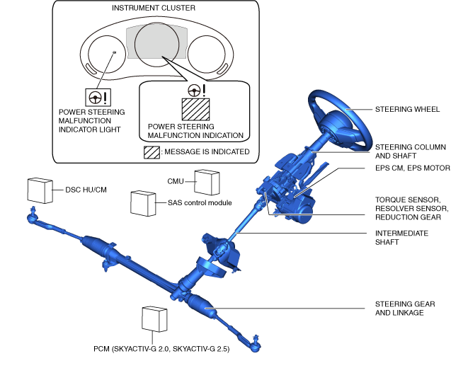
Structural View
am3zzn00009182
|
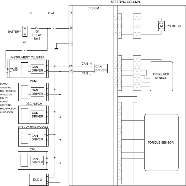
System Wiring Diagram
am3zzn00007894
|
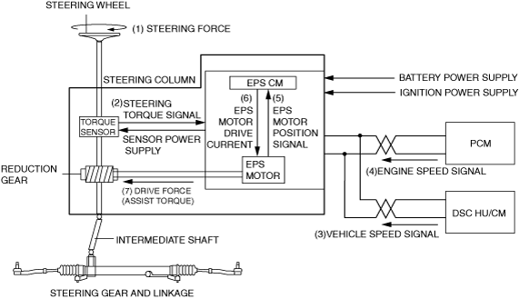
Operation
1.Steering force (1) generated by the driver’s steering wheel operation is detected by the torque sensor built into the steering column and shaft, and it is output (2) to the EPS CM as a steering torque signal.
2.The EPS CM calculates optimum assist force based on the steering torque signal (2) from the torque sensor, the vehicle speed signal (3) from the DSC HU/CM and engine speed signal (4) from the PCM, and EPS motor position information (5) from the EPS motor, and outputs (6) electric current to drive the EPS motor.
3.The EPS motor drive force (assist torque) generated by the EPS motor drive current (6) from the EPS CM is transmitted (7) to the intermediate shaft via the reduction gear to assist the driver’s steering operation.
am3zzn00009183
|