SHIFT AND SELECT MECHANISM [C66M-R]
SHIFT AND SELECT MECHANISM [C66M-R]
SM2334044
id0515m8283900
Purpose, Function
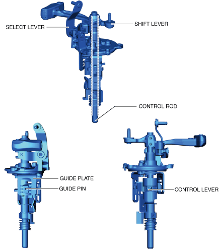
Construction
am3zzn00008959
|
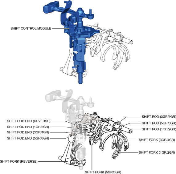
Shift control module
-
• The moving parts of the shift control module are vertically positioned.
 am3zzn00008960• In this module, the control lever which moves the shift rod end is directly assembled to the control rod. In addition, because the control rod moves up and down, the weight of the control rod is utilized when the control rod moves down.
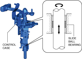
Slide ball bearing
-
• A slide ball bearing has been adopted to the sliding area between the control rod and the transaxle case, and between the control rod and the control case.am3zzn00008929• In this part, the bearing case moves in the drive and thrust directions.• Compared to the conventional bushing, sliding resistance between the control rod and the transaxle case, and between the control rod and the control case has been reduced.
Operation
-
Note
-
• Shifting operations from neutral to each gear are explained in this section.
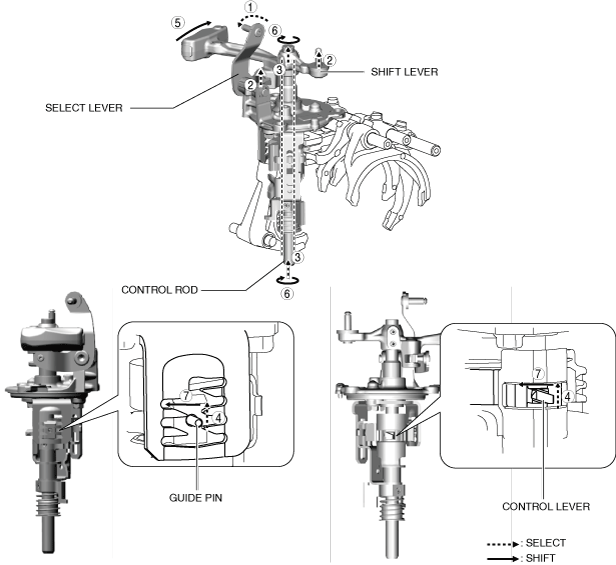
1GR
am3zzn00008961
|

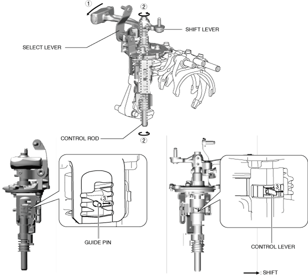
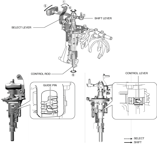
1.When the shift lever in the cabin is tilted to the left to shift to 1GR, the select lever moves in the direction of arrow 1 shown in the figure.
2.Following the movement of the select lever, the shift lever moves in the direction of arrow 2 shown in the figure.
3.Following the movement of the select lever, the control rod moves in the direction of arrow 3 shown in the figure.
4.Following the movement of the select lever, the control lever and the guide pin move in the direction of arrow 4 shown in the figure.
5.When the shift lever in the cabin is tilted forward to shift to 1GR, the shift lever in the engine compartment moves in the direction of arrow 5 shown in the figure.
6.Following the movement of the shift lever in the engine compartment, the control rod moves in the direction of arrow 6 shown in the figure.
7.Following the movement of the shift lever in the engine compartment, the control lever and the guide pin move in the direction of arrow 7 shown in the figure.
am3zzn00008962
|

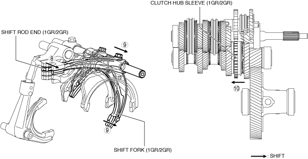
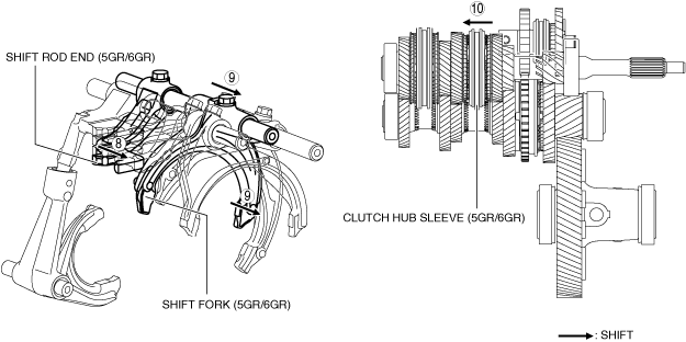
8.Because the control rod turns with the control lever, the control lever pushes the shift rod end and moves it in the direction of arrow 8 shown in the figure.
9.The shift rod end and the shift fork are integrated with the shift rod. Therefore, the movement of the shift rod end is transmitted to the shift fork via the shift rod, and the shift fork moves in the direction of arrow 9.
10.The shift fork moves the clutch hub sleeve in the direction of arrow 10 shown in the figure.
11.The shift change to 1GR is completed.
2GR
am3zzn00008963
|
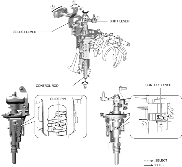
1.When the shift lever in the cabin is tilted to the left to shift to 2GR, the select lever moves in the direction of arrow 1 shown in the figure.
2.Following the movement of the select lever, the shift lever moves in the direction of arrow 2 shown in the figure.
3.Following the movement of the select lever, the control rod moves in the direction of arrow 3 shown in the figure.
4.Following the movement of the select lever, the control lever and the guide pin move in the direction of arrow 4 shown in the figure.
5.When the shift lever in the cabin is tilted rearward to shift to 2GR, the shift lever in the engine compartment moves in the direction of arrow 5 shown in the figure.
6.Following the movement of the shift lever in the engine compartment, the control rod moves in the direction of arrow 6 shown in the figure.
7.Following the movement of the shift lever in the engine compartment, the control lever and the guide pin move in the direction of arrow 7 shown in the figure.
am3zzn00008964
|
8.Because the control rod turns with the control lever, the control lever pushes the shift rod end and moves it in the direction of arrow 8 shown in the figure.
9.The shift rod end and the shift fork are integrated with the shift rod. Therefore, the movement of the shift rod end is transmitted to the shift fork via the shift rod, and the shift fork moves in the direction of arrow 9.
10.The shift fork moves the clutch hub sleeve in the direction of arrow 10 shown in the figure.
11.The shift change to 2GR is completed.
3GR
am3zzn00008965
|
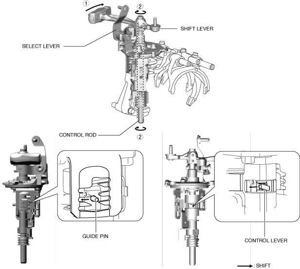
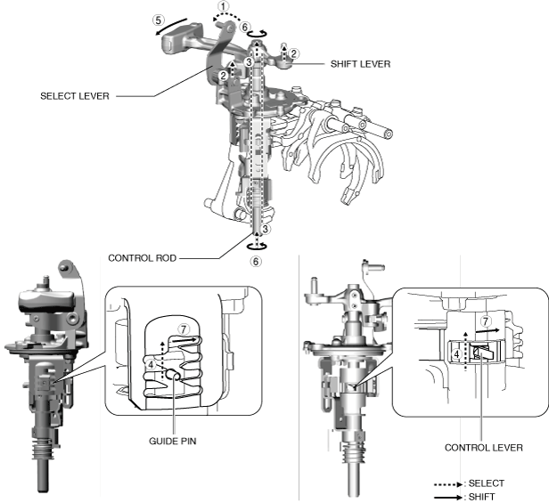
1.When the shift lever in the cabin is tilted forward to shift to 3GR, the shift lever in the engine compartment moves in the direction of arrow 1 shown in the figure.
2.Following the movement of the shift lever in the engine compartment, the control rod moves in the direction of arrow 2 shown in the figure.
3.Following the movement of the shift lever in the engine compartment, the control lever and the guide pin move in the direction of arrow 3 shown in the figure.
am3zzn00008966
|
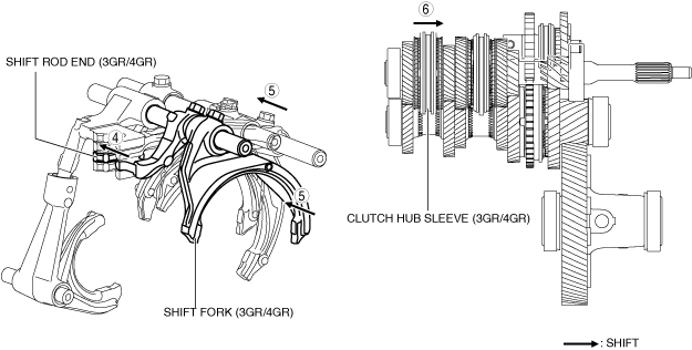
4.Because the control rod turns with the control lever, the control lever pushes the shift rod end and moves it in the direction of arrow 4 shown in the figure.
5.The shift rod end and the shift fork are integrated with the shift rod. Therefore, the movement of the shift rod end is transmitted to the shift fork via the shift rod, and the shift fork moves in the direction of arrow 5.
6.The shift fork moves the clutch hub sleeve in the direction of arrow 6 shown in the figure.
7.The shift change to 3GR is completed.
4GR
am3zzn00008967
|
1.When the shift lever in the cabin is tilted rearward to shift to 4GR, the shift lever in the engine compartment moves in the direction of arrow 1 shown in the figure.
2.Following the movement of the shift lever in the engine compartment, the control rod moves in the direction of arrow 2 shown in the figure.
3.Following the movement of the shift lever in the engine compartment, the control lever and the guide pin move in the direction of arrow 3 shown in the figure.
am3zzn00008968
|

4.Because the control rod turns with the control lever, the control lever pushes the shift rod end and moves it in the direction of arrow 4 shown in the figure.
5.The shift rod end and the shift fork are integrated with the shift rod. Therefore, the movement of the shift rod end is transmitted to the shift fork via the shift rod, and the shift fork moves in the direction of arrow 5.
6.The shift fork moves the clutch hub sleeve in the direction of arrow 6 shown in the figure.
7.The shift change to 4GR is completed.
5GR
am3zzn00008969
|
1.When the shift lever in the cabin is tilted to the right to shift to 5GR, the select lever moves in the direction of arrow 1 shown in the figure.
2.Following the movement of the select lever, the shift lever moves in the direction of arrow 2 shown in the figure.
3.Following the movement of the select lever, the control rod moves in the direction of arrow 3 shown in the figure.
4.Following the movement of the select lever, the control lever and the guide pin move in the direction of arrow 4 shown in the figure.
5.When the shift lever in the cabin is tilted forward to shift to 5GR, the shift lever in the engine compartment moves in the direction of arrow 5 shown in the figure.
6.Following the movement of the shift lever in the engine compartment, the control rod moves in the direction of arrow 6 shown in the figure.
7.Following the movement of the shift lever in the engine compartment, the control lever and the guide pin move in the direction of arrow 7 shown in the figure.
am3zzn00008970
|

8.Because the control rod turns with the control lever, the control lever pushes the shift rod end and moves it in the direction of arrow 8 shown in the figure.
9.The shift rod end and the shift fork are integrated with the shift rod. Therefore, the movement of the shift rod end is transmitted to the shift fork via the shift rod, and the shift fork moves in the direction of arrow 9.
10.The shift fork moves the clutch hub sleeve in the direction of arrow 10 shown in the figure.
11.The shift change to 5GR is completed.
6GR
am3zzn00008971
|
1.When the shift lever in the cabin is tilted to the right to shift to 6GR, the select lever moves in the direction of arrow 1 shown in the figure.
2.Following the movement of the select lever, the shift lever moves in the direction of arrow 2 shown in the figure.
3.Following the movement of the select lever, the control rod moves in the direction of arrow 3 shown in the figure.
4.Following the movement of the select lever, the control lever and the guide pin move in the direction of arrow 4 shown in the figure.
5.When the shift lever in the cabin is tilted rearward to shift to 6GR, the shift lever in the engine compartment moves in the direction of arrow 5 shown in the figure.
6.Following the movement of the shift lever in the engine compartment, the control rod moves in the direction of arrow 6 shown in the figure.
7.Following the movement of the shift lever in the engine compartment, the control lever and the guide pin move in the direction of arrow 7 shown in the figure.
am3zzn00008972
|
8.Because the control rod turns with the control lever, the control lever pushes the shift rod end and moves it in the direction of arrow 8 shown in the figure.
9.The shift rod end and the shift fork are integrated with the shift rod. Therefore, the movement of the shift rod end is transmitted to the shift fork via the shift rod, and the shift fork moves in the direction of arrow 9.
10.The shift fork moves the clutch hub sleeve in the direction of arrow 10 shown in the figure.
11.The shift change to 6GR is completed.
Reverse
am3zzn00008973
|
1.When the shift lever in the cabin is tilted to the left to shift to the reverse gear, the select lever moves in the direction of arrow 1 shown in the figure.
2.Following the movement of the select lever, the shift lever moves in the direction of arrow 2 shown in the figure.
3.Following the movement of the select lever, the control rod moves in the direction of arrow 3 shown in the figure.
4.Following the movement of the select lever, the control lever and the guide pin move in the direction of arrow 4 shown in the figure.
5.When the shift lever in the cabin is tilted forward to shift to the reverse gear, the shift lever in the engine compartment moves in the direction of arrow 5 shown in the figure.
6.Following the movement of the shift lever in the engine compartment, the control rod moves in the direction of arrow 6 shown in the figure.
7.Following the movement of the shift lever in the engine compartment, the control lever and the guide pin move in the direction of arrow 7 shown in the figure.
am3zzn00008974
|
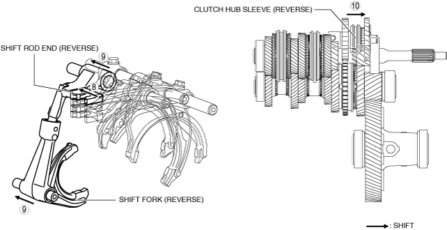
8.Because the control rod turns with the control lever, the control lever pushes the shift rod end and moves it in the direction of arrow 8 shown in the figure.
9.The shift rod end and the shift fork are integrated with the shift rod. Therefore, the movement of the shift rod end is transmitted to the shift fork via the shift rod, and the shift fork moves in the direction of arrow 9.
10.The shift fork moves the clutch hub sleeve in the direction of arrow 10 shown in the figure.
11.The shift change to the reverse gear is completed.