BEARING PRELOAD ADJUSTMENT
BEARING PRELOAD ADJUSTMENT
SM2841732
id051500169700
Primary Shaft Preload Adjustment
1.Measure the thickness of the straight edge which is used for measurements.
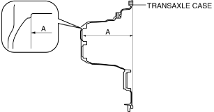
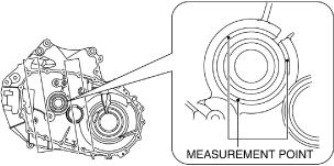
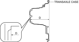
2.Measure distance A of the transaxle case using the following procedure.
bc61um00000083
|
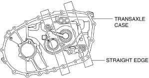
- (1)Place two straight edges on the transaxle case as shown in the figure.
-
 bc61um00000179
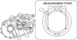
- (2)Set up 3 measurement points of your choosing on the shim assembly area of the transaxle case as shown in the figure.
-
bc61um00000180
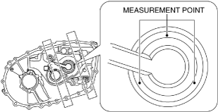
- (3)Using a commercially available depth gauge, measure the distance to each measurement point from the straight edge.
-
-
Caution
-
• When measuring the distance to the measurement point from the straight edge, do not allow the depth gauge head to contact the shim assembly area.
-
- (4)Calculate the average value measured in Step 3 using the following formula.
-
-
• (Value of first measurement + value of second measurement + value of third measurement) / 3 = Average measured values.
-
Calculation example
-
• Value of first measurement 224.380 mm {8.83386 in}• Value of second measurement 224.381 mm {8.83390 in}• Value of third measurement 224.379 mm {8.83382 in}• ( 224.380 mm {8.83386 in} + 224.381 mm {8.83390 in} + 224.379 mm {8.83382 in}) / 3 224.380 mm {8.83386 in}
-
- (5)Calculate distance A of the transaxle case using the following formula.
-
-
• Average of measured values – straight edge thickness = Distance A
-
Calculation example
-
• Straight edge thickness 5.000 mm {0.1969 in}• Average of measured values 224.380 mm {8.83386 in}• 224.380 mm {8.83386 in} – 5.000 mm {0.1969 in} 219.380 mm {8.63701 in}
-
3.Measure distance B of the transaxle case using the following procedure.
bc61um00000181
|
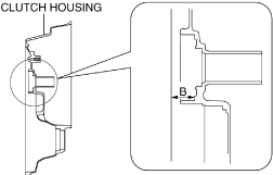
- (1)Set two straight edges on the clutch housing as shown in the figure.
-
bc61um00000182

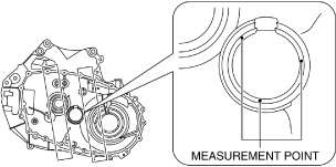
- (2)Set up 3 measurement points of your choosing on the ball bearing assembly area of the clutch housing as shown in the figure.
-
bc61um00000183
- (3)Using a commercially available depth gauge, measure the distance to each measurement point from the straight edge.
-
-
Caution
-
• When measuring the distance to the measurement points from the straight edge, do not allow the depth gauge head to contact the ball bearing assembly area.
-
- (4)Calculate the average value measured in Step 3 using the following formula.
-
-
• (Value of first measurement + value of second measurement + value of third measurement) / 3 = Average measured values.
-
Calculation example
-
• Value of first measurement 30.575 mm {1.2037 in}• Value of second measurement 30.577 mm {1.2038 in}• Value of third measurement 30.577 mm {1.2038 in}• ( 30.575 mm {1.2037 in} + 30.577 mm {1.2038 in} + 30.577 mm {1.2038 in}) / 3 30.576 mm {1.2038 in}
-
- (5)Calculate distance B of the clutch housing using the following formula.
-
-
• Average of measured values – straight edge thickness = Distance B
-
Calculation example
-
• Straight edge thickness 5.000 mm {0.1969 in}• Average of measured values 30.576 mm {1.2038 in}• 30.576 mm {1.2038 in} – 5.000 mm {0.1969 in} 25.576 mm {1.0069 in}
-
4.Measure distance C of the primary shaft component using the following procedure.
bc61um00000184
|
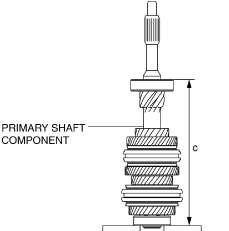
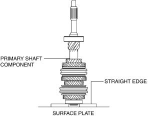
- (1)Place two straight edges on the surface plate as shown in the figure and set the primary shaft component on top of them.
-
bc61um00000185
- (2)Set up 3 measurement points of your choosing on the ball bearing as shown in the figure.
-
bc61um00000186
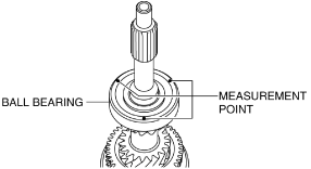
- (3)Using a commercially available height gauge, measure the distance to each measurement point from the straight edge.
- (4)Calculate the average of the value measured in Step 3 using the following formula, and use the average of the measured value for distance C of the primary shaft component.
-
-
• (Value of first measurement + value of second measurement + value of third measurement) / 3 = Distance C
-
Calculation example
-
• Value of first measurement 243.591 mm {9.59020 in}• Value of second measurement 243.592 mm {9.59024 in}• Value of third measurement 243.593 mm {9.59028 in}• ( 243.591 mm {9.59020 in} + 243.592 mm {9.59024 in} + 243.593 mm {9.59028 in}) / 3 243.592 mm {9.59024 in}
-
5.Select the primary shaft shim using the following procedure.
- (1)Calculate the clearance (clearance D) between the transaxle case and the primary shaft component using the following formula.
-
-
• Distance A + Distance B – Distance C = Clearance D
-
Calculation example
-
• Distance A 219.380 mm {8.63701 in}• Distance B 25.576 mm {1.0069 in}• Distance C 243.592 mm {9.59024 in}• 219.380 mm {8.63701 in} + 25.576 mm {1.0069 in} – 243.592 mm {9.59024 in} 1.364 mm {0.05370 in}
-
- (2)Based on the calculated clearance D, select a shim of the appropriate thickness from the following table.
-
Clearance D measured value
Appropriate shim thickness (mm {IN})
Equal to or more (mm {IN})
Less than (mm {IN})
1.570 {0.06181}1.610 {0.06339}1.550 {0.06102}1.520 {0.05984}1.570 {0.06181}1.500 {0.05906}1.470 {0.05787}1.520 {0.05984}1.450 {0.05709}1.420 {0.05591}1.470 {0.05787}1.400 {0.05512}1.370 {0.05394}1.420 {0.05591}1.350 {0.05315}1.320 {0.05197}1.370 {0.05394}1.300 {0.05118}1.270 {0.050}1.320 {0.05197}1.250 {0.04921}1.220 {0.04803}1.270 {0.050}1.200 {0.04724}1.170 {0.04606}1.220 {0.04803}1.150 {0.04528}1.120 {0.04409}1.170 {0.04606}1.100 {0.04331}1.070 {0.04213}1.120 {0.04409}1.050 {0.04134}1.020 {0.04016}1.070 {0.04213}1.000 {0.03937}0.970 {0.0382}1.020 {0.04016}0.950 {0.0374}0.920 {0.0362}0.970 {0.0382}0.900 {0.0354}0.870 {0.0343}0.920 {0.0362}0.850 {0.0335}0.820 {0.0323}0.870 {0.0343}0.800 {0.0315}0.770 {0.0303}0.820 {0.0323}0.750 {0.0295}0.720 {0.0283}0.770 {0.0303}0.700 {0.0276}0.680 {0.0268}0.720 {0.0283}0.650 {0.0256}
Secondary Shaft Preload Adjustment
1.Measure the thickness of the straight edge which is used for measurements.
2.Measure distance E of the transaxle case using the following procedure.
bc61um00000085
|
- (1)Place two straight edges on the transaxle case as shown in the figure.
-
bc61um00000187

- (2)Set up 3 measurement points of your choosing on the shim assembly area of the transaxle case as shown in the figure.
-
bc61um00000188
- (3)Using a commercially available depth gauge, measure the distance to each measurement point from the straight edge.
-
-
Caution
-
• When measuring the distance to the measurement point from the straight edge, do not allow the depth gauge head to contact the shim assembly area.
-
- (4)Calculate the average value measured in Step 3 using the following formula.
-
-
• (Value of first measurement + value of second measurement + value of third measurement) / 3 = Average measured values.
-
Calculation example
-
• Value of first measurement 223.223 mm {8.78831 in}• Value of second measurement 223.219 mm {8.78815 in}• Value of third measurement 223.222 mm {8.78827 in}• ( 223.223 mm {8.78831 in} + 223.219 mm {8.78815 in} + 223.222 mm {8.78827 in}) / 3 223.221 mm {8.78823 in}
-
- (5)Calculate distance E of the transaxle case using the following formula.
-
-
• Average of measured values – straight edge thickness = Distance E
-
Calculation example
-
• Straight edge thickness 5.000 mm {0.1969 in}• Average of measured values 223.221 mm {8.78823 in}• 223.221 mm {8.78823 in} – 5.000 mm {0.1969 in} 218.221 mm {8.59138 in}
-
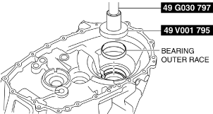
3.Measure distance F of the transaxle case using the following procedure.
bc61um00000189
|
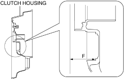
- (1)Set two straight edges on the clutch housing as shown in the figure.
-
bc61um00000190

- (2)Set up 3 measurement points of your choosing on the ball bearing assembly area of the clutch housing as shown in the figure.
-
bc61um00000191
- (3)Using a commercially available depth gauge, measure the distance to each measurement point from the straight edge.
-
-
Caution
-
• When measuring the distance to the measurement point from the straight edge, do not allow the depth gauge head to contact the bearing outer race assembly area.
-
- (4)Calculate the average value measured in Step 3 using the following formula.
-
-
• (Value of first measurement + value of second measurement + value of third measurement) / 3 = Average measured values.
-
Calculation example
-
• Value of first measurement 61.154 mm {2.4076 in}• Value of second measurement 61.153 mm {2.4076 in}• Value of third measurement 61.153 mm {2.4076 in}• ( 61.154 mm {2.4076 in} + 61.153 mm {2.4076 in} + 61.153 mm {2.4076 in}) / 3 61.153 mm {2.4076 in}
-
- (5)Calculate distance F of the clutch housing using the following formula.
-
-
• Average of measured values – straight edge thickness = Distance F
-
Calculation example
-
• Straight edge thickness 5.000 mm {0.1969 in}• Average of measured values 61.153 mm {2.4076 in}• 61.153 mm {2.4076 in} – 5.000 mm {0.1969 in} 56.153 mm {2.2107 in}
-
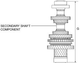
4.Measure distance G of the secondary shaft component using the following procedure.
bc61um00000192
|
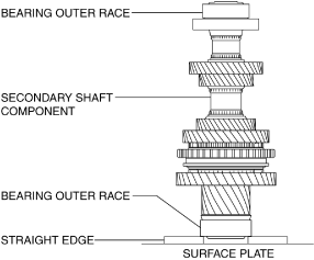
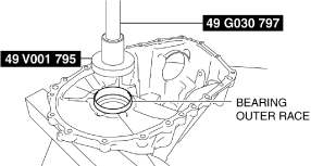
- (1)Place two straight edges on the surface plate as shown in the figure and set the bearing outer race and secondary shaft component on top of them.
-
bc61um00000148
- (2)Rotate the secondary shaft component to its rotational direction to engage the taper roller bearing and the bearing outer race assembled to the clutch housing smoothly.
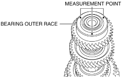
- (3)Set up 3 measurement points of your choosing on the bearing outer race as shown in the figure.
-
bc61um00000193
- (4)Using a commercially available height gauge, measure the distance to each measurement point from the straight edge.
- (5)Calculate the average of the value measured in Step 4 using the following formula, and use the average of the measured value for distance G of the secondary shaft component.
-
-
• (Value of first measurement + value of second measurement + value of third measurement) / 3 = Distance G
-
Calculation example
-
• Value of first measurement 273.274 mm {10.7588 in}• Value of second measurement 273.270 mm {10.7587 in}• Value of third measurement 273.273 mm {10.7588 in}• ( 273.274 mm {10.7588 in} + 273.270 mm {10.7587 in} + 273.273 mm {10.7588 in}) / 3 273.272 mm {10.7587 in}
-
5.Select the secondary shaft shim using the following procedure.
- (1)Calculate the clearance (clearance H) between the transaxle case and the primary shaft component using the following formula.
-
-
• Distance E + Distance F – Distance G = Clearance H
-
Calculation example
-
• Distance E 218.221 mm {8.59138 in}• Distance F 56.153 mm {2.2107 in}• Distance G 273.272 mm {10.7587 in}• 218.221 mm {8.59138 in} + 56.153 mm {2.2107 in} – 273.272 mm {10.7587 in} 1.102 mm {0.04339 in}
-
- (2)Based on the calculated clearance H, select a shim of the appropriate thickness from the following table.
-
Clearance H measured value
Appropriate shim thickness (mm {IN})
Equal to or more (mm {IN})
Less than (mm {IN})
1.331 {0.05240}1.355 {0.05335}1.500 {0.05906}1.281 {0.05043}1.331 {0.05240}1.450 {0.05709}1.231 {0.04846}1.281 {0.05043}1.400 {0.05512}1.181 {0.04650}1.231 {0.04846}1.350 {0.05315}1.131 {0.04453}1.181 {0.04650}1.300 {0.05118}1.081 {0.04256}1.131 {0.04453}1.250 {0.04921}1.031 {0.04059}1.081 {0.04256}1.200 {0.04724}0.981 {0.0386}1.031 {0.04059}1.150 {0.04528}0.931 {0.0367}0.981 {0.0386}1.100 {0.04331}0.881 {0.0347}0.931 {0.0367}1.050 {0.04134}0.831 {0.0327}0.881 {0.0347}1.000 {0.03937}0.781 {0.0307}0.831 {0.0327}0.950 {0.0374}0.731 {0.0288}0.781 {0.0307}0.900 {0.0354}0.681 {0.0268}0.731 {0.0288}0.850 {0.0335}0.631 {0.0248}0.681 {0.0268}0.800 {0.0315}0.581 {0.0229}0.631 {0.0248}0.750 {0.0295}0.531 {0.0209}0.581 {0.0229}0.700 {0.0276}0.495 {0.0195}0.531 {0.0209}0.650 {0.0256}
Differential Preload Adjustment
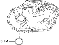
1.Assemble a new shim of the same thickness as the removed shim.
bc61um00000150
|
-
Caution
-
• Preload cannot be measured accurately if the shim is reused. An used shim is deformed by the pressure applied during assembly.
2.Assemble the bearing outer race to the transaxle case using the SSTs.
bc61um00000149
|
3.Assemble the bearing outer race to the clutch housing using the SSTs.
bc61um00000151
|
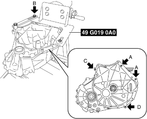
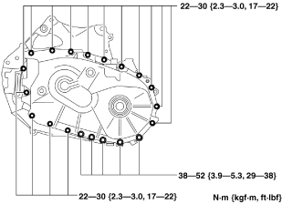
4.Assemble the SST to the clutch housing.
bc61um00000126
|
-
Bolt A
-
Part No.: 99450 1055 or M10 ×1.25 length 55 mm {2.2 in}, and nut (M10 ×1.25)
-
Bolt A tightening torque
-
38—52 N·m {3.9—5.3 kgf·m, 29—38 ft·lbf}
-
Bolt B
-
SST (49 G019 033 part of 49 G019 0A0)
-
Bolt B tightening torque
-
88—118 N·m {9.0—12 kgf·m, 65—87 ft·lbf}
-
Bolt C
-
Part No.: 9YA02 1080 or M10 ×1.5 length 55 mm {2.2 in}
-
Bolt C tightening torque
-
38—52 N·m {3.9—5.3 kgf·m, 29—38 ft·lbf}
-
Bolt D
-
Part No.: 99450 1030 or M10 ×1.25 length 30 mm {2.2 in}
-
Bolt D tightening torque
-
38—52 N·m {3.9—5.3 kgf·m, 29—38 ft·lbf}
5.Measure the outer dimension of the pinion shaft and record the measurement.
bc62zm00000055
|
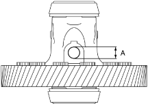
A :Pinion shaft outer dimension (17 mm {0.67 in} or 18 mm {0.71 in})
-
Note
-
• Measure the pinion shaft outer dimension and record the measurement to select the SST which is used to measure the ring gear and differential preload.
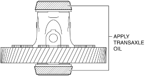
6.Apply transaxle oil to the roller area of the taper roller bearing on the differential.
bc61um00000153
|
7.Assemble the differential to the clutch housing.
bc61um00000154
|

8.Assemble the transaxle case to the clutch housing.
bc61um00000101
|
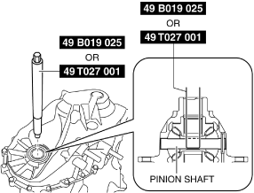
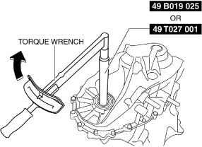
9.Set the SST so that its end engages the pinion shaft of the differential.
bc62zm00000056
|
-
Note
-
• Select the SST by matching it to the pinion shaft outer dimension measured in Step 5.
-
― Pinion shaft outer dimension 17 mm {0.67 in}: SST (49 B019 025)― Pinion shaft outer dimension 18 mm {0.71 in}: SST (49 T027 001)
-
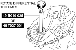
10.Rotate the differential ten times using the SST to engage the taper roller bearing and the bearing outer race smoothly.
bc62zm00000057
|
11.Rotate the differential once as shown in the figure taking approx. 6 s, and measure the differential preload.
bc62zm00000058
|
-
Standard preload
-
0.7—1.7 N·m {7.2—17 kgf·cm, 6.2—15 in·lbf}
-
• If the measured preload is within the specification, the shim thickness is the same as the removed one and there is no problem, therefore the “Differential Preload Adjustment” procedure is finished.• If not within the specification, perform “Shim selection calculation”. (See Shim selection calculation.)
Shim selection calculation
1.Calculate the preload gap by subtracting the measured preload value from constant number A.
-
• Constant number A 1.2 N·m {12 kgf·cm, 11 in·lbf}• 1.2 N·m {12 kgf·cm, 11 in·lbf} – measured preload value = preload gap
-
Calculation example
-
• Measured preload value 2.5 N·m {25 kgf·cm, 22 in·lbf}• 1.2 N·m {12 kgf·cm, 11 in·lbf} – 2.5 N·m {25 kgf·cm, 22 in·lbf} -1.3 N·m {13 kgf·cm, 12 in·lbf}
2.Calculate the shim thickness gap by multiplying the preload gap by constant number B.
-
• Constant number B 0.083 mm/N·m {0.008 mm/kgf·cm, 0.0004 in/in·lbf}• Preload gap x 0.083 mm/N·m {0.008 mm/kgf·cm, 0.0004 in/in·lbf} = shim thickness gap
-
Calculation example
-
• Preload gap -1.3 N·m {-13 kgf·cm, -12 in·lbf}• -1.3 N·m {-13 kgf·cm, -12 in·lbf} x 0.083 mm/N·m {0.008 mm/kgf·cm, 0.0004 in/in·lbf} -0.108 mm {-0.00425 in}
3.Calculate the shim thickness calculated value by adding the shim thickness gap to the thickness of the shim used in the measurement.
-
• Shim thickness gap + thickness of shim used in measurement = shim thickness calculated value
-
Calculation example
-
• Shim thickness gap -0.108 mm {-0.00425 in}• Thickness of shim used in measurement 0.9000 mm {0.03543 in}• -0.108 mm {-0.00425 in} + 0.9000 mm {0.03543 in} 0.792 mm {0.0312 in}
4.Based on the shim thickness calculated value, select a shim of the appropriate thickness.
|
Shim thickness calculated value |
Appropriate shim thickness (mm {IN}) |
|
|---|---|---|
|
Equal to or more (mm {IN}) |
Less than (mm {IN}) |
|
|
1.220 {0.04803}
|
1.260 {0.04961}
|
1.350 {0.05315}
|
|
1.170 {0.04606}
|
1.220 {0.04803}
|
1.300 {0.05118}
|
|
1.120 {0.04409}
|
1.170 {0.04606}
|
1.250 {0.04921}
|
|
1.070 {0.04213}
|
1.120 {0.04409}
|
1.200 {0.04724}
|
|
1.020 {0.04016}
|
1.070 {0.04213}
|
1.150 {0.04528}
|
|
0.970 {0.0382}
|
1.020 {0.04016}
|
1.100 {0.04331}
|
|
0.920 {0.0362}
|
0.970 {0.0382}
|
1.050 {0.04134}
|
|
0.870 {0.0343}
|
0.920 {0.0362}
|
1.000 {0.03937}
|
|
0.820 {0.0323}
|
0.870 {0.0343}
|
0.950 {0.0374}
|
|
0.770 {0.0303}
|
0.820 {0.0323}
|
0.900 {0.0354}
|
|
0.720 {0.0283}
|
0.770 {0.0303}
|
0.850 {0.0335}
|
|
0.670 {0.0264}
|
0.720 {0.0283}
|
0.800 {0.0315}
|
|
0.620 {0.0244}
|
0.670 {0.0264}
|
0.750 {0.0295}
|
|
0.570 {0.0224}
|
0.620 {0.0244}
|
0.700 {0.0276}
|
|
0.520 {0.0205}
|
0.570 {0.0224}
|
0.650 {0.0256}
|
|
0.470 {0.0185}
|
0.520 {0.0205}
|
0.600 {0.0236}
|
|
0.420 {0.0165}
|
0.470 {0.0185}
|
0.550 {0.0217}
|
|
0.390 {0.0154}
|
0.420 {0.0165}
|
0.50 {0.0197}
|
-
Selection example
-
• Because shim thickness calculated value 0.792 mm {0.0312 in} applies to 0.775 mm {0.0305 in} or more and less than 0.825 mm {0.0325 in}, a shim of 0.800 mm {0.0315 in} thickness is selected.
-
Note
-
• The preload gap is the difference between the central value of the standard preload value and the measured preload value.• Constant number A, 1.2 N·m {12 kgf·cm, 11 in·lbf} is the central value of the standard preload value.• The shim thickness gap is the difference between the thickness of the removed shim and the thickness of an appropriate shim. In the formula to calculate the shim thickness gap, the shim thickness gap is calculated by multiplying the preload gap with constant number B.• Constant number B is the shim thickness which varies each time the preload changes by 1.0 N·m {10 kgf·cm, 8.9 in·lbf}. Because the shim thickness changes 0.1 mm {0.004 in} when the preload changes 1.2 N·m {12 kgf·cm, 11 in·lbf}, the quotient is 0.083 mm/N·m {0.008 mm/kgf·cm 0.0004 in/in·lbf}.