DIFFERENTIAL BACKLASH ADJUSTMENT
DIFFERENTIAL BACKLASH ADJUSTMENT
SM2841729
id051500169400
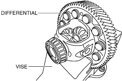
1.Secure the differential in a vice.
bc61um00000067
|
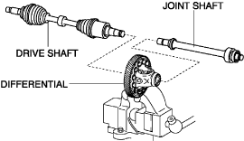
2.Assemble the drive shaft and the joint shaft to the differential.
bc61um00000196
|
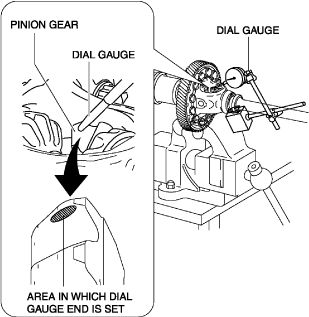
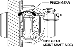
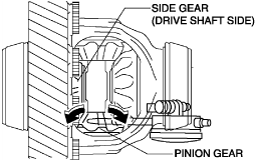
3.Set the dial gauge with the measuring probe attached perpendicularly to the area shown in the figure for the pinion gear.
bc61um00000195
|
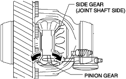
4.Measure the side gear on the joint shaft side and the pinion gear backlash using the following procedure:
bc61um00000197
|
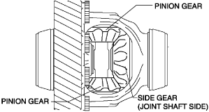
- (1)Affix the side gear on the joint shaft side by hand.
- (2)Measure the backlash by moving the pinion gear with the dial gauge that has been set and determine measured value A.
-
 bc61um00000198
-
Caution
-
• Because a difference occurs in the backlash measurement value if the secured side gear moves, move the pinion gear by hand so that the secured side gear does not move.
-
- (3)Measure the opposite of the pinion gear backlash in the same way as procedure 2 in Step 4 and determine measured value B.
-
bc61um00000199
- (4)Calculate the average value of measured values A and B using the following formula and determine the backlash measurement value on the joint shaft side of the pinion gear.
-
-
• (Measured value A + measured value B)/2 = backlash measurement value on joint shaft side
-
5.Measure the side gear on the drive shaft side and the pinion gear backlash using the following procedure:
bc61um00000200
|
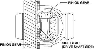
- (1)Affix the side gear on the drive shaft side by hand.
- (2)Measure the backlash by moving the pinion gear that the dial gauge has been set and determine measured value C.
-
bc61um00000201
-
Caution
-
• Because a difference occurs in the backlash measurement value if the secured side gear moves, move the pinion gear by hand so that the secured side gear does not move.
-
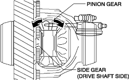
- (3)Measure the opposite of the pinion gear backlash in the same way as procedure 2 in Step 5 and determine measured value D.
-
bc61um00000202
- (4)Calculate the average value of measured values C and D using the following formula and determine the backlash measurement value on the drive shaft side of the pinion gear.
-
-
• (Measured value C + measured value D)/2 = backlash measurement value on drive shaft side
-
6.Verify that the backlash on the joint shaft and drive shaft sides is within the specification.
-
Differential pinion gear backlash
-
Specification: 0.05—0.15 mm {0.002—0.005 in}
-
• If the measured backlash for each is within the specification, the thrust washer thickness is the same as the removed one and there is no problem, therefore the “DIFFERENTIAL BACKLASH ADJUSUTMENT” procedure is finished.• If not within the specification, perform “Thrust Washer Selection Calculation”. (See Thrust Washer Selection Calculation.)• If it exceeds the specification even when a 0.95 mm {0.037 in} thick thrust washer is used, replace the differential case.
Thrust Washer Selection Calculation
-
Note
-
• Perform the thrust washer selection calculation for each on the drive shaft and joint shaft sides.
1.Calculate the backlash gap by subtracting constant number A from backlash measurement value.
-
• Constant number A 0.090 mm {0.0035 in}• Backlash measurement value – 0.090 mm {0.0035 in} = backlash gap
-
Calculation example
-
• Backlash measurement value 0.165 mm {0.00650 in}• 0.165 mm {0.00650 in} – 0.090 mm {0.0035 in} 0.075 mm {0.0030 in}
2.Calculate the thrust washer thickness gap by multiplying the backlash gap by constant number B.
-
• Constant number B 1.25 mm/mm {1.333 in/in}• Backlash gap × 1.25 mm/mm {1.333 in/in} = thrust washer thickness gap
-
Calculation example
-
• Backlash gap 0.075 mm {0.0030 in}• 0.075 mm {0.0030 in} × 1.25 mm/mm {1.333 in/in} 0.094 mm {0.0037 in}
3.Calculate the thrust washer thickness calculated value by adding the thrust washer thickness gap to the thickness of the thrust washer used in the measurement.
-
• Thickness of thrust washer used in measurement + thrust washer thickness gap = thrust washer thickness calculated value
-
Calculation example
-
• Thickness of thrust washer used in measurement 0.810 mm {0.8103 mm}• Thrust washer thickness gap 0.094 mm {0.0037 in}• 0.810 mm {0.0319 in} + 0.094 mm {0.0037 in} 0.904 mm {0.0356 in}
4.Calculate the thrust washer thickness on the opposite side in the same way.
5.Based on each thrust washer thickness calculated value, select each thrust washer of the appropriate thickness.
-
Caution
-
• Select the same thickness of the thrust washers on the drive shaft and joint shaft sides.However, if the measurement value cannot be adjusted within the specification, select the different thickness of the thrust washer.
|
Thrust washer thickness calculated value |
Appropriate thrust washer thickness (mm {IN}) |
|
|---|---|---|
|
Equal to or more (mm {IN}) |
Less than (mm {IN}) |
|
|
0.925 {0.0364}
|
1.025 {0.04035}
|
0.95 {0.037}
|
|
0.875 {0.0344}
|
0.925 {0.0364}
|
0.90 {0.035}
|
|
0.825 {0.0325}
|
0.875 {0.0344}
|
0.85 {0.033}
|
|
0.775 {0.0305}
|
0.825 {0.0325}
|
0.80 {0.031}
|
|
0.675 {0.0266}
|
0.775 {0.0305}
|
0.75 {0.030}
|
-
Note
-
• Constant number A, 0.090 mm {0.0035 in} is the backlash median value of the specification.• The backlash gap is the difference between the backlash median value of the specification and the backlash measurement value.• Constant number B is the thrust washer thickness which varies each time the backlash changes by 1.0 mm {0.039 in}.Because the thrust washer thickness changes 0.1 mm {0.004 in} when the backlash changes 0.08 mm {0.003 in}, the quotient is 1.25 mm/mm {1.333 in/in}.• The thrust washer thickness gap is the difference between the thickness of the thrust washer used in the measurement and the thickness of an appropriate thrust washer.In the formula to calculate the thrust washer thickness gap, the thrust washer thickness gap is calculated by multiplying the backlash gap with constant number B.