PRIMARY SHAFT COMPONENT INSPECTION
PRIMARY SHAFT COMPONENT INSPECTION
SM2841723
id051500168800
Gear Inspection
1. Inspect the gears for damage, wear, or loss.
-
• If there is any malfunction, replace the gear.
2.Inspect the gears and synchronizer rings for damage and wear on contact surfaces.
-
• If there is any malfunction, replace the gear.
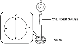
3.Measure the inner diameter of the gear using a cylinder gauge in X and Y directions as shown in the figure.
bc61um00000024
|
-
• If it exceeds the maximum specification, replace the gear.
Inner diameter of gear
|
Measurement location |
Specification (mm {IN}) |
Maximum (mm {IN}) |
|---|---|---|
|
3rd gear
|
37.01 {1.4571}
|
37.02 {1.4575}
|
|
4th gear
|
32.81 {1.2917}
|
32.82 {1.2921}
|
|
5th gear
|
42.01 {1.6539}
|
42.02 {1.6543}
|
|
6th gear
|
37.01 {1.4571}
|
37.02 {1.4575}
|
Primary Shaft Inspection
1.Inspect the spline for damage and wear.
-
• If there is any malfunction, replace the primary shaft.
2.Inspect the gear area for damage, wear, and loss.
-
• If there is any malfunction, replace the primary shaft.
3.Measure the runout of the primary shaft.
- (1)Set the primary shaft on V-blocks so that the V-blocks support the primary shaft journal as shown in the figure.
-
 bc61um00000025
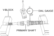
- (2)Measure the runout of the position shown in the figure for the primary shaft using a dial gauge.
-
-
• If it exceeds the maximum specification, replace the primary shaft.
-
Runout of primary shaft
-
Maximum: 0.05 mm {0.002 in}
-
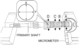
4.Measure the outer diameter of the primary shaft using a micrometer. Measurement positions total eight and are in the X and Y directions, at four points (A, B, C, and D) as shown in the figure.
bc61um00000026
|
-
• If it is less than the minimum specification, replace the primary shaft.
Outer diameter of primary shaft
|
Measurement location |
Specification (mm {IN}) |
Minimum (mm {IN}) |
|---|---|---|
|
Measurement location
|
Specification (mm {IN})
|
32.76 {1.2898}
|
|
Measurement location
|
Specification (mm {IN})
|
36.96 {1.4551}
|
|
Measurement location
|
Specification (mm {IN})
|
36.96 {1.4551}
|
|
Measurement location
|
Specification (mm {IN})
|
41.96 {1.652}
|
Synchronizer Ring Inspection
1.Inspect the teeth of the synchronizer ring for damage, wear, or loss.
-
• If there is any malfunction, replace the synchronizer ring.
2.Inspect the taper surface for wear or loss.
-
• If there is any malfunction, replace the synchronizer ring.
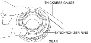
3.While holding the synchronizer ring and gear with your fingers as shown in the figure, measure the clearance of the synchronizer ring and gear side surface around the entire circumference using a thickness gauge.
bc61um00000027
|
-
• If it is less than the minimum specification, replace the synchronizer ring.
Clearance between synchronizer ring and gear
|
Measurement location |
Specification (mm {IN}) |
Minimum (mm {IN}) |
|---|---|---|
|
Synchronizer ring (3GR)
|
0.97 {0.038}
|
0.32 {0.013}
|
|
Synchronizer ring (4GR)
|
1.05 {0.0413}
|
0.40 {0.016}
|
|
Synchronizer ring (5GR)
|
1.15 {0.0453}
|
0.50 {0.020}
|
|
Synchronizer ring (6GR)
|
1.15 {0.0453}
|
0.50 {0.020}
|
Clutch Hub Component Inspection
1.Inspect the clutch hub sleeve and clutch hub operation.
-
• If there is any malfunction, replace the malfunctioning part.
2.Inspect the spline for damage, wear or loss.
-
• If there is any malfunction, replace the malfunctioning part.
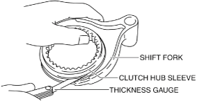
3. While holding the clutch hub sleeve and shift fork together with your hand as shown in the figure, measure the clearance between the shift fork and clutch hub sleeve groove using a thickness gauge.
bc61um00000028
|
-
• If it exceeds the maximum, replace the clutch hub sleeve and shift fork as a set.
Clearance between shift fork and clutch hub sleeve groove
|
Measurement location |
Specification (mm {IN}) |
Maximum (mm {IN}) |
|---|---|---|
|
Shift fork (3GR/4GR)
|
0.225 {0.00886}
|
0.40 {0.016}
|
|
Shift fork (5GR/6GR)
|
0.225 {0.00886}
|
0.40 {0.016}
|