PRIMARY SHAFT COMPONENT PREINSPECTION
PRIMARY SHAFT COMPONENT PREINSPECTION
SM2841721
id051500168600
3rd Gear Thrust Clearance Inspection
1.Adjust the SST (49 0107 680A), point the transaxle case assembly surface of the clutch housing upward, and then level it.
2.Assemble the primary shaft component to the clutch housing.
bc61um00000118
|
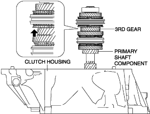
3.Set the dial gauge to the position of the arrow shown in the figure.
4.Hold the primary shaft component by hand.
-
Note
-
• To prevent error during the thrust clearance measurement, hold the primary shaft component by hand so that the primary shaft component does not move.
5.Move the 3rd gear in the axial direction and measure the 3rd gear thrust clearance.
-
• If it exceeds the maximum specification, inspect the 3rd gear and surrounding parts for damage and wear and replace the malfunctioning part.
-
3rd gear thrust clearance
-
Specification: 0.257 mm {0.0101 in}Maximum: 0.417 mm {0.0164 in}
4th Gear Thrust Clearance Inspection
1.Insert a thickness gauge into the clearance between the 4th gear and the ball bearing.
bc61um00000119
|
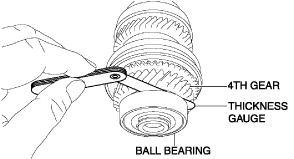
2.Rotate the thickness gauge one full rotation along the primary shaft and measure the 4th gear thrust clearance.
-
• If it exceeds the maximum specification, inspect the 4th gear and surrounding parts for damage and wear and replace the malfunctioning part.
-
4th gear thrust clearance
-
Specification: 0.325 mm {0.0128 in}Maximum: 0.489 mm {0.0193 in}
5th Gear Thrust Clearance Inspection
1.Adjust the SST (49 0107 680A), point the transaxle case assembly surface of the clutch housing upward, and then level it.
2.Assemble the primary shaft component to the clutch housing.
bc61um00000120
|
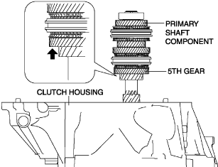
3.Set the dial gauge to the position of the arrow shown in the figure.
4.Hold the primary shaft component by hand.
-
Note
-
• To prevent error during the thrust clearance measurement, hold the primary shaft component by hand so that the primary shaft component does not move.
5.Move the 5th gear in the axial direction and measure the 5th gear thrust clearance.
-
• If it exceeds the maximum specification, inspect the 5th gear and surrounding parts for damage and wear and replace the malfunctioning part.
-
5th gear thrust clearance
-
Specification: 0.192 mm {0.00756 in}Maximum: 0.324 mm {0.0128 in}
6th Gear Thrust Clearance Inspection
1.Adjust the SST (49 0107 680A), point the transaxle case assembly surface of the clutch housing upward, and then level it.
2.Assemble the primary shaft component to the clutch housing.
bc61um00000121
|
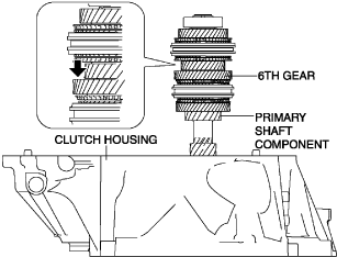
3.Set the dial gauge to the position of the arrow shown in the figure.
4.Hold the primary shaft component by hand.
-
Note
-
• To prevent error during the thrust clearance measurement, hold the primary shaft component by hand so that the primary shaft component does not move.
5.Move the 6th gear in the axial direction and measure the 6th gear thrust clearance.
-
• If it exceeds the maximum specification, inspect the 6th gear and surrounding parts for damage and wear and replace the malfunctioning part.
-
6th gear thrust clearance
-
Specification: 0.262 mm {0.0103 in}Maximum: 0.398 mm {0.0157 in}