TIMING CHAIN ASSEMBLY
TIMING CHAIN ASSEMBLY
SM2841617
id011000505600
-
Caution
-
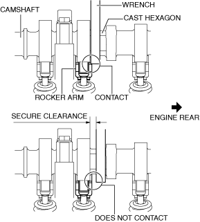
• If the camshaft is rotated with the timing chain removed and the piston at the top dead center position, the valve may contact the piston and the engine could be damaged. When rotating the camshaft with the timing chain removed, rotate it after lowering the piston from the top dead center position.• When rotating the camshaft using a wrench on the cast hexagon, the wrench may contact the rocker arm and damage the rocker arm. To prevent damage to the rocker arm when holding the camshaft on the cast hexagon, use a wrench on the rear side of the engine as shown in the figure to secure a clearance between the cam.
 am3uuw00008968• When installing the oil pan, refer to the Oil Pan Installation Note and apply the silicone sealant correctly. If the silicone sealant application position is incorrect or there is any break in the application track, engine oil leakage will occur due to a poor seal.
-
Note
-
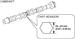
• Width at the cast hexagon of the camshaft is 22—24 mm {0.87—0.94 in}.bpe5ue00000032
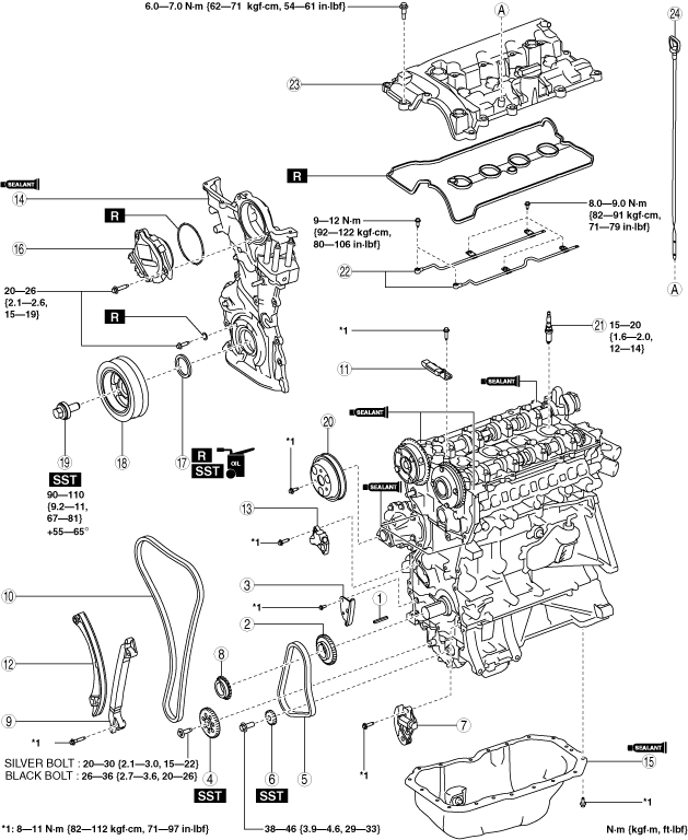
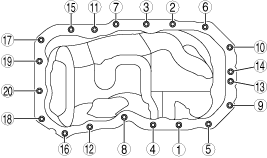
1.Assemble in the order indicated in the table.
bpe5ue00000036
|
|
1
|
Key
|
|
2
|
Oil pump drive sprocket
|
|
3
|
Oil pump chain guide
|
|
4
|
Oil pump driven sprocket
(See Oil Pump Chain Assembly Note.)
|
|
5
|
Oil pump chain
(See Oil Pump Chain Assembly Note.)
|
|
6
|
Balancer shaft sprocket
(See Oil Pump Chain Assembly Note.)
|
|
7
|
Oil pump chain tensioner
(See Oil Pump Chain Assembly Note.)
|
|
8
|
Crankshaft sprocket
|
|
9
|
Chain guide (No.2)
|
|
10
|
Timing chain
(See Timing Chain Assembly Note.)
|
|
11
|
Chain guide (No.1)
(See Timing Chain Assembly Note.)
|
|
12
|
Tensioner arm
(See Timing Chain Assembly Note.)
|
|
13
|
Chain tensioner
(See Timing Chain Assembly Note.)
|
|
14
|
Engine front cover
|
|
15
|
Oil pan
(See Oil Pan Assembly Note.)
|
|
16
|
Electric variable valve timing motor/driver
|
|
17
|
Front oil seal
(See Front Oil Seal Assembly Note.)
|
|
18
|
Crankshaft pulley
|
|
19
|
Crankshaft pulley lock bolt
|
|
20
|
Water pump pulley
|
|
21
|
Spark plug
|
|
22
|
Oil shower pipe
|
|
23
|
Cylinder head cover
|
|
24
|
Dipstick
|
Oil Pump Chain Assembly Note
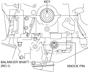
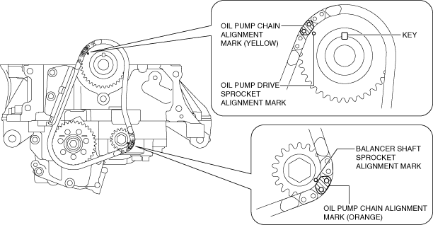
1.Verify that the key and knock pin are aligned to the positions shown in the figure.
bpe1ze00000070
|
-
• If they are not in the positions shown in the figure, rotate the crankshaft and balancer shaft (No.1) to set cylinder No.1 to top dead center (TDC).
2.Temporarily assemble the oil pump driven sprocket.
3.Temporarily tighten the oil pump driven sprocket installation bolt.
4.Align the oil pump chain alignment mark with the balancer shaft sprocket alignment mark.
bpe1ze00000071
|
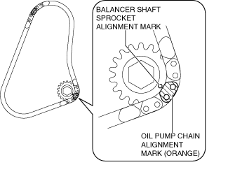
5.Install the oil pump chain and balancer shaft sprocket as a single unit while aligning the alignment marks on each sprocket and oil pump chain as shown in the figure.
bpe1ze00000072
|
6.Temporarily tighten the balancer shaft sprocket installation bolt.
7.Install the oil pump chain tensioner.
-
Caution
-
• At this stage, do not remove the wire or paper clip installed to the oil pump chain tensioner.
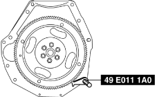
8.Hold the crankshaft using the SST.
bpe1ze00000096
|
9.Tighten the oil pump driven sprocket installation bolt.
-
Tightening torque
-
Silver bolt: 20—30 N·m {2.1—3.0 kgf·m, 15—22 ft·lbf}Black bolt: 26—36 N·m {2.7—3.6 kgf·m, 20—26 ft·lbf}
10.Tighten the balancer shaft sprocket installation bolt.
-
Tightening torque
-
38—46 N·m {3.9—4.6 kgf·m, 29—33 ft·lbf}
11.Remove the wire or paper clip installed to the oil pump chain tensioner and apply tension to the oil pump chain.
-
• If a new oil pump chain tensioner is used, remove the installed stopper.
Timing Chain Assembly Note
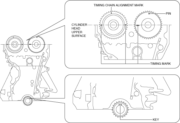
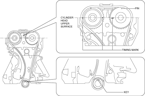
1.Verify that the timing marks and the key are aligned to the position shown in the figure.
bpe5ue00000009
|
-
Note
-
• The timing mark of SKYACTIV-G 2.5 is not parallel with the upper surface of the cylinder head.
-
• If they are not in the position shown in the figure, rotate the camshaft and crankshaft to set the cylinder No.1 top dead center (TDC).
2.Install the timing chain while aligning the marks on each sprocket and the timing chain as shown in the figure.
bpe5ue00000053
|

3.Install the tensioner arm.
4.Install the chain tensioner.
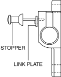
5.After installing the chain tensioner, remove the installed wire or paper clip, and then apply tension to the timing chain. (Chain tensioner (type A))
-
• If a new chain tensioner is used, remove the installed stopper.am3uuw00008861
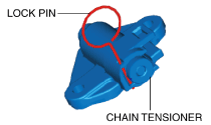
6.After installing the timing chain tensioner, remove the installed rod, and then apply tension to the timing chain. (Chain tensioner (type B))
-
• If a new chain tensioner is used, remove the installed lock pin.ac5uuw00006989
7.Install the chain guide (No.1).
8.Verify that there is no looseness in the timing chain, and re-verify that each sprocket is in the specified location.
9.Rotate the crankshaft clockwise two turns and inspect the valve timing.
bpe5ue00000010
|
-
Note
-
• The timing mark of SKYACTIV-G 2.5 is not parallel with the upper surface of the cylinder head.
Engine Front Cover Assembly Note
-
Note
-
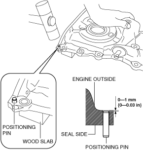
• For a new engine front cover, the positioning pins in the two locations shown in the figure project to the outside of the engine.bpe1ze00000006
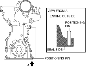
1.If the engine front cover is newly replaced, tap the positioning pins in the two locations to the seal surface side.
bpe5ue00000033
|
2.Completely clean and remove any oil, dirt, sealant or other foreign matter that may be adhering to the engine front cover, cylinder head, and cylinder block.
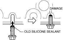
3.When reusing the engine front cover installation bolts, clean any old sealant from the bolts.
-
Caution
-
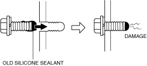
• Apply the silicon sealant in a single, unbroken line.• To prevent silicone sealant from hardening, adhere the engine front cover to the cylinder block within 10 min. after silicone sealant is applied. Tighten the installation bolts completely soon after adhering.• Using bolts with the old silicone sealant adhering could cause cracks in the cylinder head and cylinder block.bpe5ue00000046
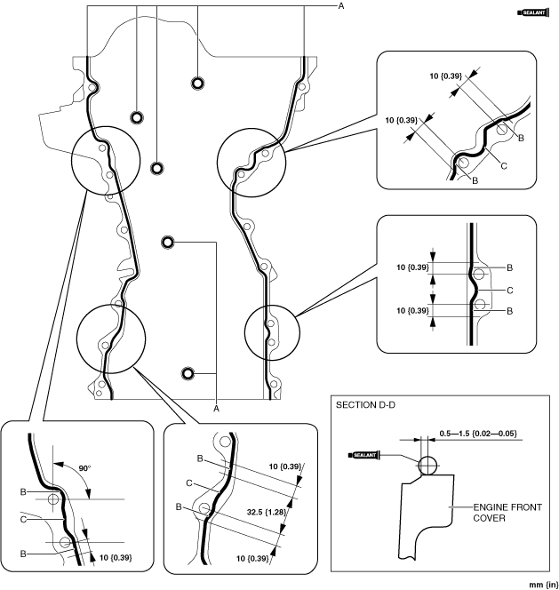
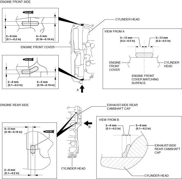
4.Apply silicone sealant to the engine front cover as shown in the figure.
bpe5ue00000034
|
-
Thickness
-
A: 2—6 mm {0.1—0.2 in}B: 4—6 mm {0.16—0.23 in}C: 4—8 mm {0.2—0.3 in}
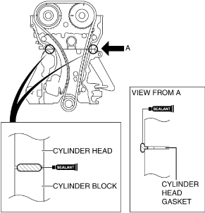
5.Apply silicone sealant to the areas shown in the figure.
am3uuw00008866
|
-
Caution
-
• Apply the silicone sealant so that it goes into the cylinder head gasket.
6.Install the engine front cover to the engine.
-
Note
-
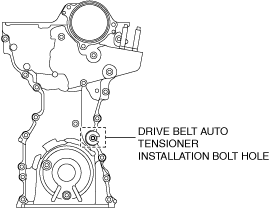
• Temporarily install an appropriate bolt to the drive belt auto tensioner installation bolt hole to prevent:
-
― A silicone sealant adhesion malfunction in the drive belt auto tensioner installation bolt hole.― A bolt mis-installation due to silicone sealant hardening.
am3uuw00008867 -
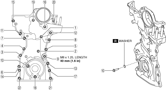
7.Prepare an appropriate M8 X 1.25 bolt (length 40 mm {1.6 in}).
-
Caution
-
• For the number 10 bolt of the tightening order, install the bolts with new washer.
8.Tighten the engine front cover installation bolts in the order shown in the figure.
bpe5ue00000035
|
-
Tightening torque
-
20—26 N·m {2.1—2.6 kgf·m, 15—19 ft·lbf}
9.Remove the bolt installed to the drive belt auto tensioner installation bolt hole when installing the drive belt auto tensioner.
Oil Pan Assembly Note
1.Completely clean and remove any oil, dirt, sealant or other foreign matter that may be adhering to the cylinder block and oil pan.
2.When reusing the oil pan installation bolts, clean any old sealant from the bolts.
-
Caution
-
• Apply the silicon sealant in a single, unbroken line around the whole perimeter.• To prevent silicone sealant from hardening, adhere the oil pan to the cylinder block within 10 min. after silicone sealant is applied. Tighten the installation bolts completely soon after adhering.• Using bolts with the old silicone sealant adhering could cause cracks in the cylinder block.ac5wzw00007109
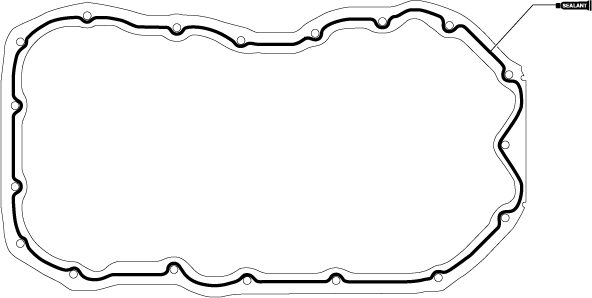
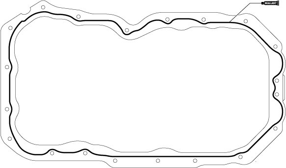
3.Apply silicone sealant to the oil pan along the inside of the bolt holes as shown in the figure.
SKYACTIV-G 2.0
ac5jjw00006425
|
-
Caution
-
• For SKYACTIV-G 2.5, also apply silicone sealant to the cylinder block.
SKYACTIV-G 2.5 oil pan
ac5jjw00006426SKYACTIV-G 2.5 cylinder block
ac5wzw00007106
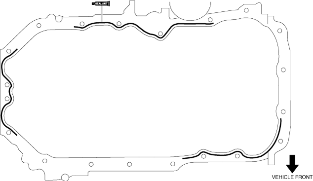
-
Thickness
-
SKYACTIV-G 2.0: 2.0—6.0 mm {0.08—0.23 in}SKYACTIV-G 2.5: 3.0—7.0 mm {0.12—0.27 in}
4.Install the oil pan using the following procedure:
-
Caution
-
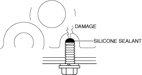
• Remove any silicone sealant which oozes out into an oil pan installation bolt hole. If silicone sealant penetrates an oil pan installation bolt hole, the cylinder block could become damaged.ac5wzw00007107
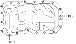
- (1)Install the oil pan to the cylinder block.
- (2)Temporarily tighten the two bolts shown in the figure.
-
bpe1ze00000081
- (3)Tighten the bolts in the order shown in the figure.
-
bpe1ze00000082
-
Tightening torque
-
8—11 N·m {82—112 kgf·cm, 71—97 in·lbf}
-
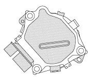
Electric Variable Valve Timing Motor/Driver Assembly Note
1.Install a new O-ring to the O-ring installation groove of the engine front cover.
-
Caution
-
• To prevent damage to the electric variable valve timing motor/driver, do not apply excessive force (force of 100 N {10.2 kgf, 22.5 lbf} or more) to the shaded areas shown in the figure.bpe1ze00000009
2.Install the electric variable valve timing motor/driver using the following procedures.
-
Note
-
• The eccentric shaft on the electric variable valve timing actuator side can be rotated to the left and right.am3uuw00009042• The electric variable valve timing motor/driver can be assembled with the joint groove of the eccentric shaft in any position, and it will not lead to vehicle damage or performance reduction.
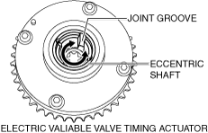
- (1)Before installation, rotate the joint on the end of the electric variable valve timing motor so that it is aligned to the joint groove on the electric variable valve timing actuator side.
-
am3uuw00009043
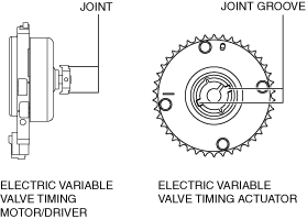
- (2)Engage the joint on the end of the electric variable valve timing motor with the joint groove on the electric variable valve timing actuator side.
- (3)Attach the seal surface.
- (4)Tighten the electric variable valve timing motor/driver installation bolts.
-
-
Tightening torque
-
20—26 N·m {2.1—2.6 kgf·m, 15—19 ft·lbf}
-
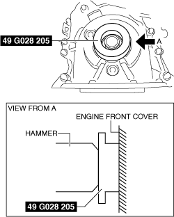
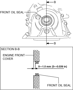
Front Oil Seal Assembly Note
1.Apply clean engine oil to the inner surface of a new front oil seal.
2.Insert the front oil seal into the engine front cover by hand.
3.Tap the oil seal in evenly using the SST and a hammer.
am3uuw00008830
|
bpe5ue00000037
|
-
Front oil seal press on amount
-
0—1.0 mm {0—0.039 in}
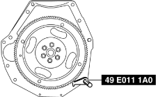
Crankshaft Pulley Lock Bolt Assembly Note
1.Hold the crankshaft using the SST.
bpe1ze00000069
|
2.Tighten the crankshaft pulley lock bolt in the order shown in the following two steps.
-
Tightening procedure
-
Step 1: 90—110 N·m {9.2—11 kgf·m, 67—81 ft·lbf}Step 2: 55—65°
Water Pump Pulley Assembly Note
-
Caution
-
• Be careful not to damage the belt groove and surface of the water pump pulley when using tools, otherwise it will cause wear, breakage, abnormal noise of the drive belt (stretch belt), damage to the pulley, and rust.
1.Install the water pump pulley to the water pump and temporarily tighten the bolt.
2.Align the water pump pulley hole with the water pump hole as shown in the figure.
bpe2ue00000081
|
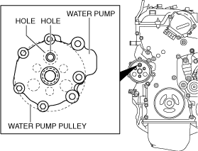
3.Insert an appropriate bolt (length 70 mm {2.8 in}) into the water pump hole shown in the figure and lock the water pump pulley against rotation.
am3uuw00008874
|
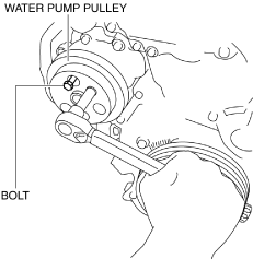
4.Completely tighten the water pump pulley bolt to the specified torque.
-
Tightening torque
-
8—11 N·m {82—112 kgf·cm, 71—97 in·lbf}
5.Remove the bolt used for locking the water pump pulley against rotation.
Oil Shower Pipe Assembly Note
1.Install the oil shower pipe in the order shown in the figure.
am3zzw00012759
|
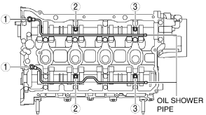
Tightening torque
|
Installation position |
Tightening torque |
|---|---|
|
1
|
9—12 N·m {92—122 kgf·cm, 80—106 in·lbf}
|
|
2, 3
|
8.0—9.0 N·m {82—91 kgf·cm, 71—79 in·lbf}
|
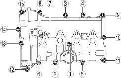
Cylinder Head Cover Assembly Note
-
Caution
-
• To assure the sealing performance of the cylinder head cover, be careful of the following:
-
― Verify that the cylinder head cover gasket is inserted into the cylinder head cover groove and install the cylinder head cover.― Completely clean and remove any oil, dirt, sealant or other foreign matter from the seal surface.
• To prevent silicone sealant from hardening, adhere the cylinder head cover and the cylinder head within 10 min. after silicone sealant is applied. Tighten the installation bolts completely soon after adhering. -
1.Insert a new cylinder head cover gasket into the cylinder head cover groove.
2.Apply silicone sealant to the areas shown in the figure.
bpe5ue00000045
|
3.Install the cylinder head cover.
4.Temporarily tighten the cylinder head cover bolts.
5.Tighten the cylinder head cover bolts in the order shown in the figure.
am3uuw00008879
|
-
Tightening torque
-
6.0—7.0 N·m {62—71 kgf·cm, 54—61 in·lbf}
6.Measure the tightening torque again and verify that it is 6.0 N·m {61 kgf·cm, 53 in·lbf} or more.