CYLINDER HEAD ASSEMBLY (I)
CYLINDER HEAD ASSEMBLY (I)
SM2841613
id011000504300
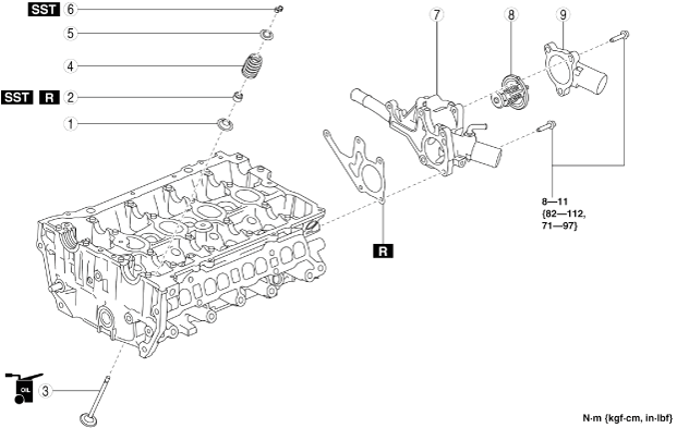
1.Assemble in the order indicated in the table.
bpe5ue00000038
|
|
1
|
Lower valve spring seat
|
|
2
|
Valve seal
(See Valve Seal Assembly Note.)
|
|
3
|
Valve
|
|
4
|
Valve spring
(See Valve Spring Assembly Note.)
|
|
5
|
Upper valve spring seat
|
|
6
|
Valve keeper
(See Valve Keeper Assembly Note.)
|
|
7
|
Water outlet
(See Water Outlet Assembly Note.)
|
|
8
|
Thermostat
(See Thermostat Assembly Note.)
|
|
9
|
Thermostat cover
|
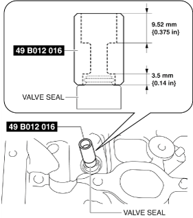
Valve Seal Assembly Note
1.Press on the valve seal to the valve guide using the SST by hand.
bpe5ue00000043
|
-
Valve seal identification color
-
IN: GREENEX: GRAY
Valve Spring Assembly Note
-
Caution
-
• The valve springs differ depending on IN and EX sides. Therefore, verify the free length or identification paint beforehand and assemble the valve springs correctly.
 bpe7ze00000013
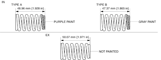
1.Assemble the valve spring with the small diameter side of the valve spring facing upward.
Valve Keeper Assembly Note
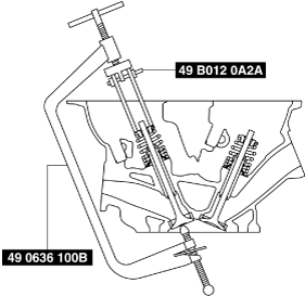
1.Install the valve keeper using the SST.
bpe1ze00000020
|
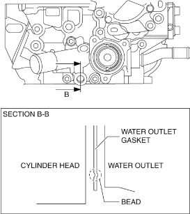
Water Outlet Assembly Note
1.Install the water outlet gasket with the bead of the gasket facing the direction shown in the figure.
bpe1ze00000021
|
2.Temporarily tighten the water outlet installation bolts.
3.Tighten bolt A of the 5 bolts shown in the figure to the specified torque first.
bpe1ze00000022
|
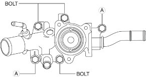
-
Tightening torque
-
8—11 N·m {82—112 kgf·cm, 71—97 in·lbf}
-
Note
-
• The tightening order for the remaining 3 bolts is optional.
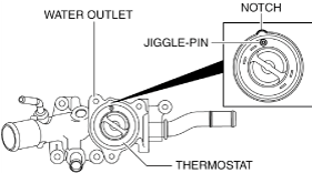
Thermostat Assembly Note
1.Install the thermostat with the jiggle pin aligned with the notch of the water outlet.
bpe1ze00000023
|