CENTER PILLAR AND SIDE SILL REMOVAL [PANEL REPLACEMENT]
CENTER PILLAR AND SIDE SILL REMOVAL [PANEL REPLACEMENT]
SM2333653
id098008753900
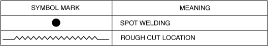
Symbol Mark
am6zzb00000392
|
Removal Procedure
Side Sill (Front-side)
1.Rough cut the 2 locations in areas A shown in the figure.
2.Drill the spot welds in the 18 locations in area B shown in the figure.
am3zzb00000461
|
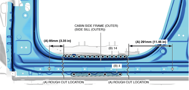
3.Remove the cabin side frame (outer) (side sill (outer)).
Center pillar and side sill component
-
Caution
-
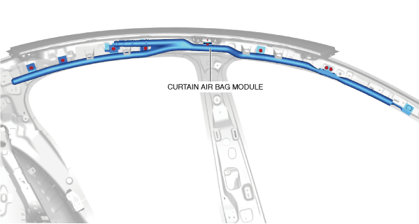
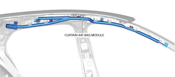
• To prevent injury, remove the curtain air bag module before performing the work.
4SD
 am3zzb00000406
5HB
am3zzb00000407
-
Caution
-
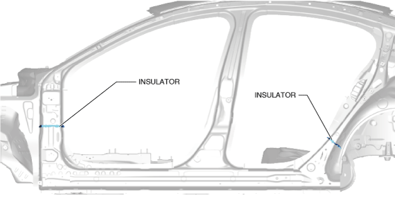
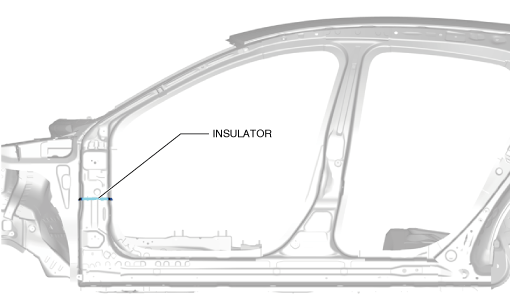
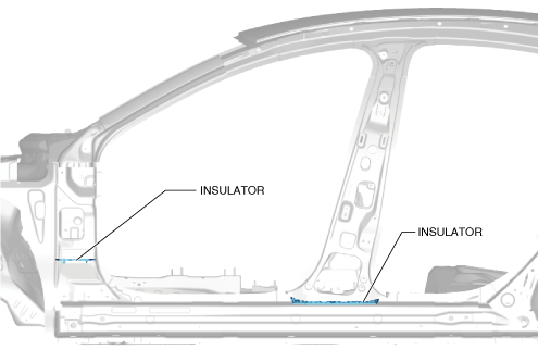
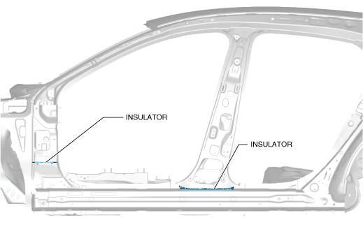
• If cutting work is done using flame, a fire could occur because insulators are inserted in the locations shown in the figure. When performing the cutting work near the insulator insert areas, avoid using flame and use an air saw or drill.
4SD
am3zzb000005005HB
am3zzb00000553
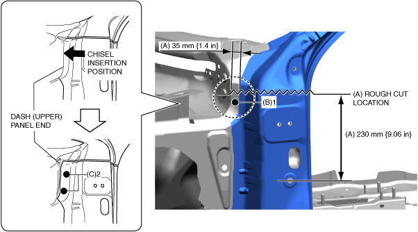
1.Rough cut area A shown in the figure.
2.Drill the spot welds in the 1 location in area B shown in the figure.
3.Insert a chisel into the position of the arrow shown in the figure, peel off the weld bond, and then move the end of the dash (upper) panel.
4.Drill the spot welds in the 2 locations in area C shown in the figure.
am3zzb00000769
|
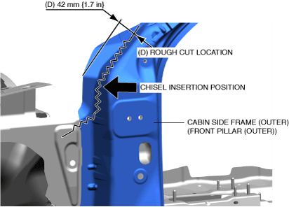
5.Rough cut area D shown in the figure.
6.Insert a chisel into the position of the arrow shown in the figure, peel off the weld bond, and then move the cut off part of the side frame outer (front pillar outer).
am3zzb00000770
|
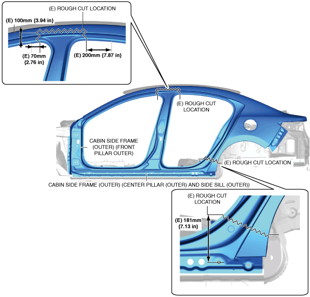
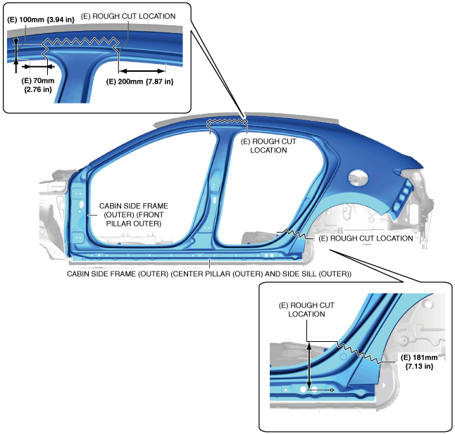
7.Rough cut the 2 locations in areas E shown in the figure.
4SD
am3zzb00000501
|
5HB
am3zzb00000554
|
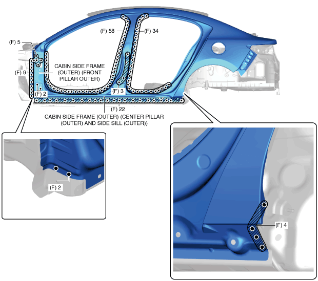
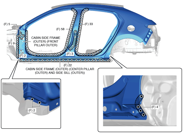
8.Drill the spot welds in the 139 locations (4SD), 138 locations (5HB) in area F shown in the figure.
4SD
am3zzb00000502
|
5HB
am3zzb00000555
|
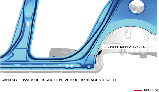
9.Insert the chisel into the location in area G shown in the figure and peel off the weld bond adhering to the wheel arch line.
4SD
am3zzb00000556
|
5HB
am3zzb00000558
|
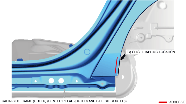
10.Remove the cabin side frame (outer) (front pillar (outer), center pillar (outer) and side sill (outer)).
-
Caution
-
• If cutting work is done using flame, a fire could occur because insulators are inserted in the locations shown in the figure. When performing the cutting work near the insulator insert areas, avoid using flame and use an air saw or drill.
4SD
am3zzb000005035HB
am3zzb00000557
11.Drill the spot welds in the 20 locations in area H shown in the figure.
-
Note
-
• When drilling the spot welds in the 20 locations in area H shown in the figure, do not drill through-holes in consideration of the workability when installing.
12.Drill the spot welds in the 4 locations in area I shown in the figure.
am3zzb00000504
|
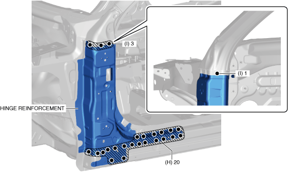
13.Remove the hinge reinforcement.
14.Drill the spot welds in the 9 locations in area J shown in the figure.
-
Note
-
• When drilling the spot welds in the 9 locations in area J shown in the figure, do not drill through-holes in consideration of the workability when installing.
15.Drill the spot welds in the 54 locations in area K shown in the figure from the interior.
16.Drill the spot welds in the 43 locations in area L shown in the figure.
am3zzb00000560
|
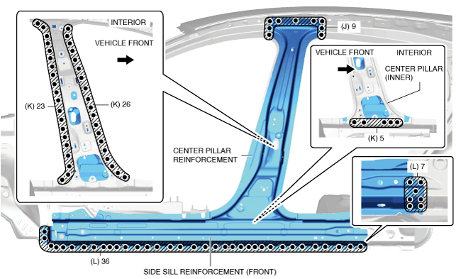
17.Remove the center pillar reinforcement and side sill reinforcement (front) at the same time.
18.Drill the spot welds in the 15 locations in area M shown in the figure.
am3zzb00000507
|
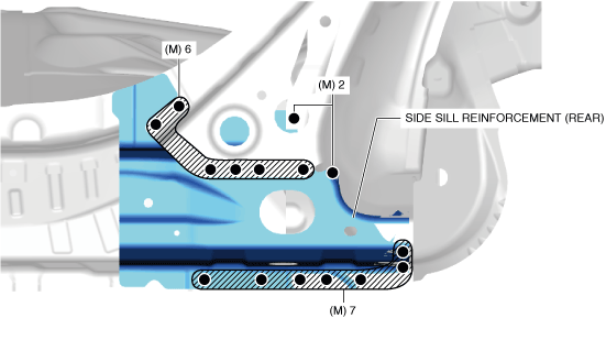
19.Remove the side sill reinforcement (rear).
20.Drill the spot welds in the 8 locations in area N shown in the figure from the interior.
am3zzb00000508
|
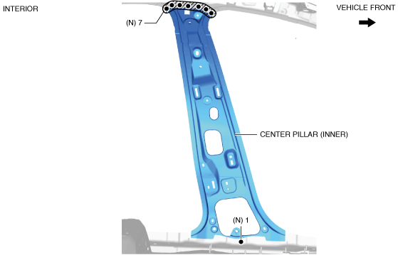
21.Remove the center pillar (inner).