AUXILIARY JACK/USB PORT INSPECTION
2016 – MX-5 – Body and Accessories
AUXILIARY JACK/USB PORT INSPECTION
Auxiliary Jack Inspection
1. Disconnect the negative battery cable. (See NEGATIVE BATTERY CABLE DISCONNECTION/CONNECTION.)
2. Remove the following parts:
a. Selector lever knob (AT) (See AUTOMATIC TRANSMISSION SHIFT MECHANISM REMOVAL/INSTALLATION.)
b. Shift lever knob (MT)
c. Shift panel component (See SHIFT PANEL REMOVAL/INSTALLATION.)
d. Upper panel (See UPPER PANEL REMOVAL/INSTALLATION.)
e. Parking brake lever boot panel (See PARKING BRAKE LEVER BOOT PANEL REMOVAL/INSTALLATION.)
f. Rear console (See REAR CONSOLE REMOVAL/INSTALLATION.)
g. Front console panel (See FRONT CONSOLE PANEL REMOVAL/INSTALLATION.)
h. Front console component (See FRONT CONSOLE REMOVAL/INSTALLATION.)
i. Side wall (See SIDE WALL REMOVAL/INSTALLATION.)
j. Auxiliary jack/USB port (See AUXILIARY JACK/USB PORT REMOVAL/INSTALLATION.)
3. Connect a commercially-available plug to the auxiliary jack/USB port.

4. Verify that the continuity between the auxiliary jack/USB port terminals is as indicated in the table.
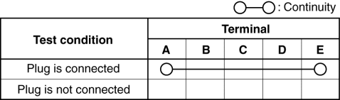
-
If not as indicated in the table, replace the auxiliary jack/USB port. (See AUXILIARY JACK/USB PORT REMOVAL/INSTALLATION.)
USB Port Inspection
1. Disconnect the negative battery cable. (See NEGATIVE BATTERY CABLE DISCONNECTION/CONNECTION.)
2. Remove the following parts:
a. Selector lever knob (AT) (See AUTOMATIC TRANSMISSION SHIFT MECHANISM REMOVAL/INSTALLATION.)
b. Shift lever knob (MT)
c. Shift panel component (See SHIFT PANEL REMOVAL/INSTALLATION.)
d. Upper panel (See UPPER PANEL REMOVAL/INSTALLATION.)
e. Parking brake lever boot panel (See PARKING BRAKE LEVER BOOT PANEL REMOVAL/INSTALLATION.)
f. Rear console (See REAR CONSOLE REMOVAL/INSTALLATION.)
g. Front console panel (See FRONT CONSOLE PANEL REMOVAL/INSTALLATION.)
h. Front console component (See FRONT CONSOLE REMOVAL/INSTALLATION.)
i. Side wall (See SIDE WALL REMOVAL/INSTALLATION.)
j. Auxiliary jack/USB port (See AUXILIARY JACK/USB PORT REMOVAL/INSTALLATION.)
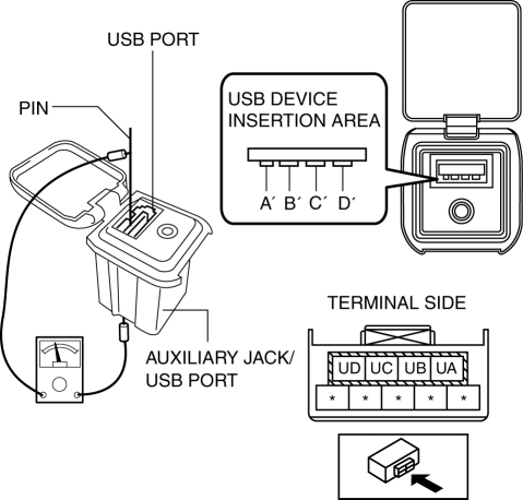
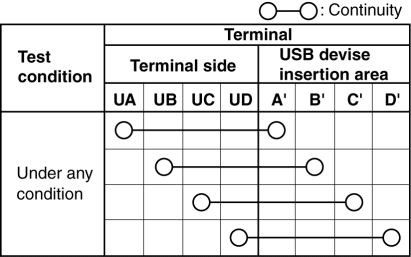
3. Insert the pins to positions A’, B’, C’, and D’ shown in the figure from the side of the USB device insertion area for the auxiliary jack/USB port, and verify the continuity at the insertion side and terminal side of the USB device.
4. Verify that the continuity at the insertion side and terminal side of the USB device is as indicated in the table.
NOTE:
-
When inspecting the USB device insertion side, touch it with a paper clip or similar thin pin without directly inserting a tester into the terminals.
-
If not as indicated in the table, replace the auxiliary jack/USB port. (See AUXILIARY JACK/USB PORT REMOVAL/INSTALLATION.)