INTAKE-AIR SYSTEM REMOVAL/INSTALLATION [SKYACTIV-G 2.0]
2016 – MX-5 – Engine
INTAKE-AIR SYSTEM REMOVAL/INSTALLATION [SKYACTIV-G 2.0]
WARNING:
-
A hot engine and intake air system can cause severe burns. Turn off the engine and wait until they are cool before removing the intake air system.
1. Disconnect the negative battery cable. (See NEGATIVE BATTERY CABLE DISCONNECTION/CONNECTION.)
2. Remove in the order indicated in the table.
3. Install in the reverse order of removal.
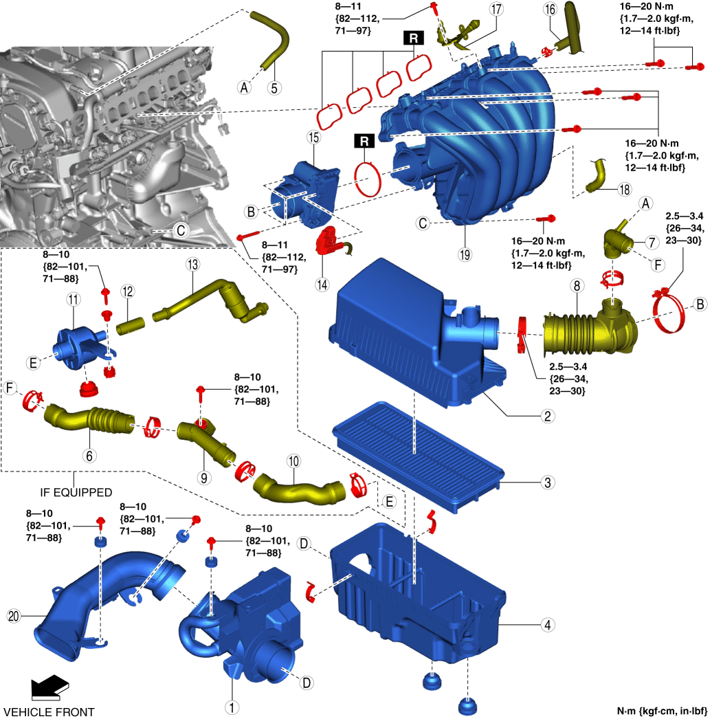
|
1 |
Resonance chamber No.1 |
|
2 |
Air cleaner cover |
|
3 |
Air cleaner element |
|
4 |
Air cleaner case |
|
5 |
Ventilation hose |
|
6 |
Air intake hose No.1 |
|
7 |
Joint pipe (See Joint Pipe Installation Note.) |
|
8 |
Air hose (See Air Hose Installation Note.) |
|
9 |
Resonance duct |
|
10 |
Air intake hose No.2 |
|
11 |
Resonance chamber No.2 |
|
12 |
Air intake hose No.3 |
|
13 |
Air intake pipe |
|
14 |
Throttle body connector |
|
15 |
Throttle body |
|
16 |
Vacuum hose |
|
17 |
Fuel hose |
|
18 |
PCV hose (See POSITIVE CRANKCASE VENTILATION (PCV) VALVE REMOVAL/INSTALLATION [SKYACTIV-G 2.0].) |
|
19 |
Intake manifold (See Intake Manifold Removal Note.) |
|
20 |
Fresh-air duct (See Fresh-air Duct Removal Note.) |
Resonance Chamber No.1 Removal Note
1. Remove the MAF sensor/IAT sensor No.1. (See MASS AIR FLOW (MAF) SENSOR/INTAKE AIR TEMPERATURE (IAT) SENSOR NO.1 REMOVAL/INSTALLATION [SKYACTIV-G 2.0].)
2. Remove the following parts as a single unit:
-
Resonance chamber No.1
-
Air cleaner cover
-
Air cleaner element
-
Air cleaner case
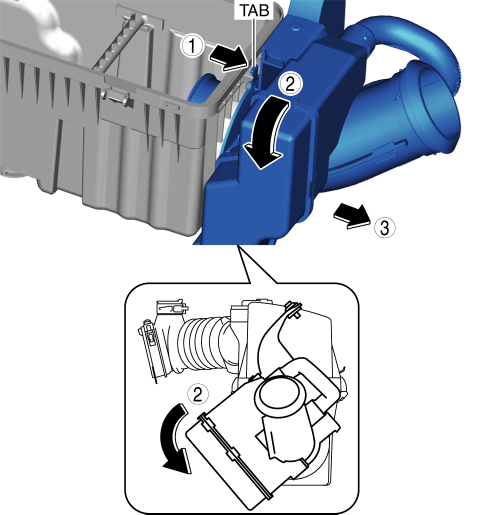
3. While moving the tab in the direction shown in the figure, rotate the resonance chamber No.1.
Intake Manifold Removal Note
1. Remove the following parts:
a. Seal cover (See SEAL COVER REMOVAL/INSTALLATION [SKYACTIV-G 2.0].)
b. Purge solenoid valve (See PURGE SOLENOID VALVE REMOVAL/INSTALLATION [SKYACTIV-G 2.0].)
c. Catch tank (See PURGE SOLENOID VALVE REMOVAL/INSTALLATION [SKYACTIV-G 2.0].)
d. Front wheel and tire (See GENERAL PROCEDURES (SUSPENSION).)
e. Front splash shield No.1 (See FRONT SPLASH SHIELD No.1 REMOVAL/INSTALLATION.)
f. Front crossmember under cover (See FRONT CROSSMEMBER UNDER COVER REMOVAL/INSTALLATION.)
g. Wiper arm and blade (See WIPER ARM AND BLADE REMOVAL/INSTALLATION.)
h. Cowl grille (See COWL GRILLE REMOVAL/INSTALLATION.)
i. Air box complete (See AIR BOX COMPLETE REMOVAL/INSTALLATION.)
2. Disconnect the MAP sensor/IAT sensor No.2 connector. (See MANIFOLD ABSOLUTE PRESSURE (MAP) SENSOR/INTAKE AIR TEMPERATURE (IAT) SENSOR NO.2 REMOVAL/INSTALLATION [SKYACTIV-G 2.0].)
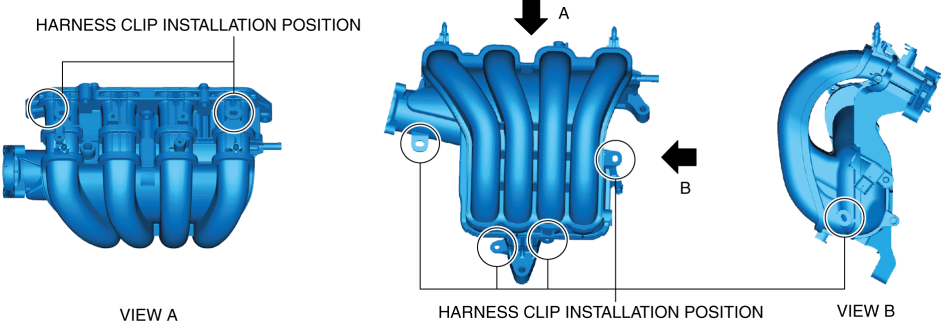
3. Disconnect the harness clip from the intake manifold as shown in the figure.
4. Remove the intake manifold.
Fresh-air Duct Removal Note
1. Remove the following parts:
a. Front bumper (See FRONT BUMPER REMOVAL.)
b. Front bumper slider (RH) (See FRONT BUMPER SLIDER REMOVAL/INSTALLATION.)
c. Front combination light (RH) (See FRONT COMBINATION LIGHT REMOVAL/INSTALLATION.)
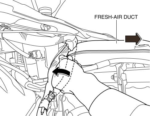
2. Disconnect the harness clip as shown in the figure.
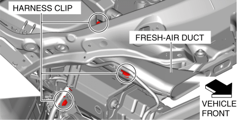
3. Remove the fresh-air duct as shown in the figure.
Fresh-air Duct Installation Note
1. Install the fresh-air duct as shown in the figure.
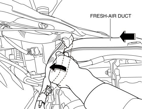
2. Connect the harness clip as shown in the figure.
3. Install the following parts:
a. Front combination light (RH) (See FRONT COMBINATION LIGHT REMOVAL/INSTALLATION.)
b. Front bumper slider (RH) (See FRONT BUMPER SLIDER REMOVAL/INSTALLATION.)
c. Front bumper (See FRONT BUMPER INSTALLATION.)
Intake Manifold Installation Note
1. Install the intake manifold.
2. Connect the harness clip from the intake manifold as shown in the figure.
3. Connect the MAP sensor/IAT sensor No.2 connector. (See MANIFOLD ABSOLUTE PRESSURE (MAP) SENSOR/INTAKE AIR TEMPERATURE (IAT) SENSOR NO.2 REMOVAL/INSTALLATION [SKYACTIV-G 2.0].)
4. Install the following parts:
a. Air box complete (See AIR BOX COMPLETE REMOVAL/INSTALLATION.)
b. Cowl grille (See COWL GRILLE REMOVAL/INSTALLATION.)
c. Wiper arm and blade (See WIPER ARM AND BLADE REMOVAL/INSTALLATION.)
d. Front crossmember under cover (See FRONT CROSSMEMBER UNDER COVER REMOVAL/INSTALLATION.)
e. Front splash shield No.1 (See FRONT SPLASH SHIELD No.1 REMOVAL/INSTALLATION.)
f. Front wheel and tire (See GENERAL PROCEDURES (SUSPENSION).)
g. Catch tank (See PURGE SOLENOID VALVE REMOVAL/INSTALLATION [SKYACTIV-G 2.0].)
h. Purge solenoid valve (See PURGE SOLENOID VALVE REMOVAL/INSTALLATION [SKYACTIV-G 2.0].)
i. Seal cover (See SEAL COVER REMOVAL/INSTALLATION [SKYACTIV-G 2.0].)
Air Intake Hose No.3 Installation Note
1. Install the air intake hose No.3 as shown in the figure.
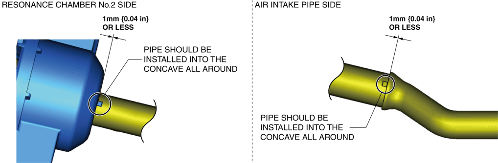
Air Intake Hose No.2 Installation Note
1. Install the air intake hose No.2 as shown in the figure.
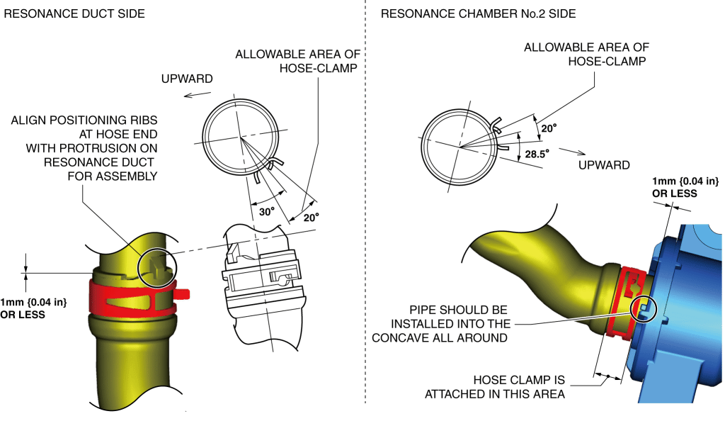
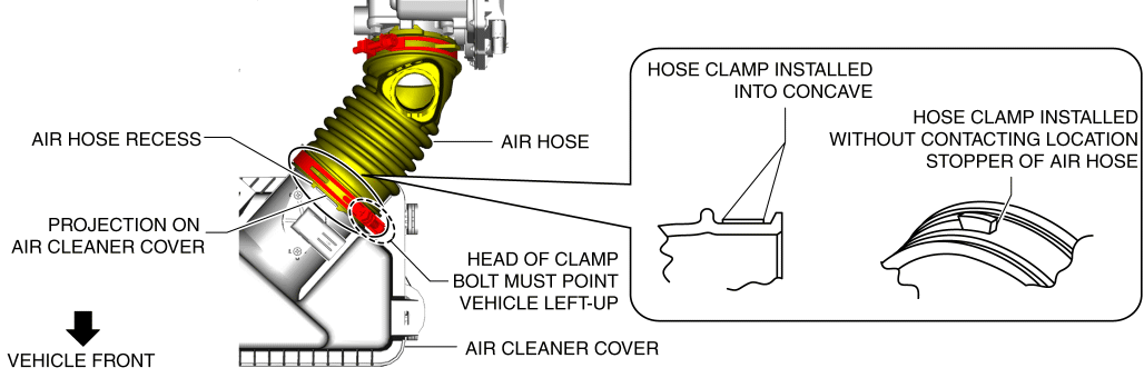
Air Hose Installation Note
1. Install the air hose as shown in the figure.
Throttle body side
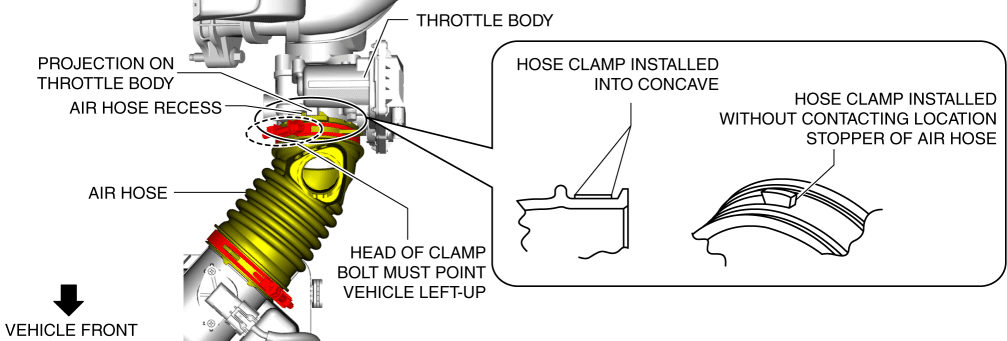
Air cleaner side
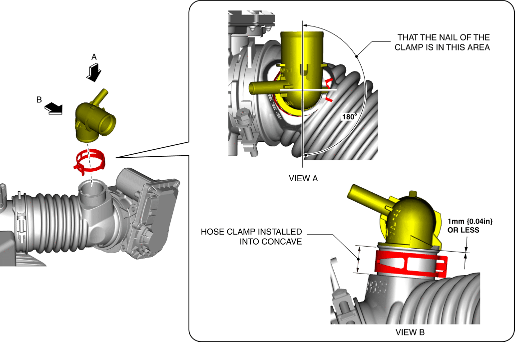
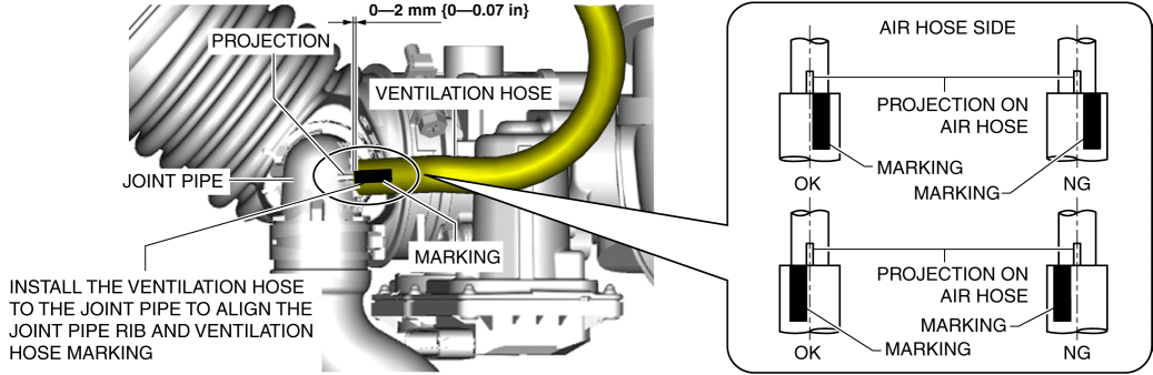
Joint Pipe Installation Note
1. Install the joint pipe as shown in the figure.
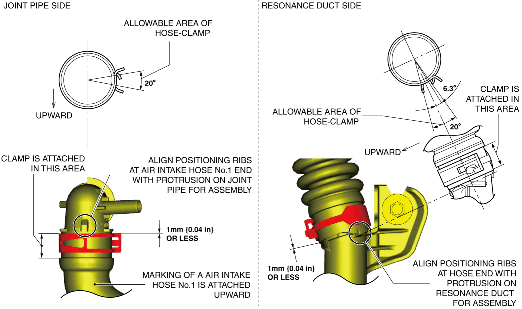
Air Intake Hose No.1 Installation Note
1. Install the air intake hose No.1 as shown in the figure.
Ventilation Hose Installation Note
1. Install the ventilation hose as shown in the figure.
Cylinder head cover side
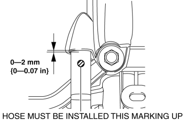
Joint pipe side
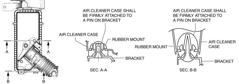
Air Cleaner Case Installation Note
1. Install the air cleaner case as shown in the figure.
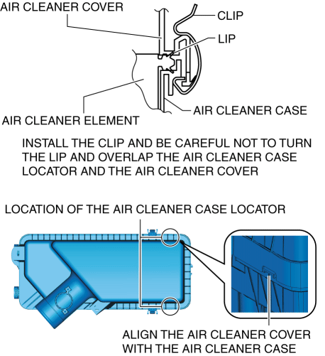
Air Cleaner Cover Installation Note
1. Install the air cleaner cover as shown in the figure.
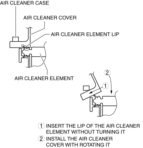
2. Secure the air cleaner cover and the air cleaner case with the clip.
Resonance Chamber No.1 Installation Note
1. Install the resonance chamber by aligning it with the air cleaner case grooves as shown in the figure and rotate the resonance chamber until the tab locks.

2. Install the following parts as a single unit:
-
Air cleaner case
-
Air cleaner element
-
Air cleaner cover
-
Resonance chamber No.1
3. Install the MAF sensor/IAT sensor No.1. (See MASS AIR FLOW (MAF) SENSOR/INTAKE AIR TEMPERATURE (IAT) SENSOR NO.1 REMOVAL/INSTALLATION [SKYACTIV-G 2.0].)