RELAY INSPECTION
2016 – MX-5 – Body and Accessories
RELAY INSPECTION
Relay Type
|
Connector type |
Part name |
|
Type A |
|
|
Type B |
|
|
Type C |
|
Type A
1. Remove the relay. (See RELAY LOCATION.)
2. Verify the continuity between relay terminals C and D.
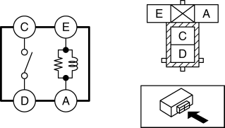
-
If it can be verified, replace the relay. (See RELAY LOCATION.)
-
If it cannot be verified, go to the next step.
3. Verify the continuity between relay terminals E and A.
-
If it can be verified, go to the next step.
-
If it cannot be verified, replace the relay. (See RELAY LOCATION.)
4. Apply battery voltage to relay terminal E, and connect terminal A to ground.
5. Verify the continuity between relay terminals C and D.
-
If it cannot be verified, replace the relay. (See RELAY LOCATION.)
Type B
1. Remove the relay. (See RELAY LOCATION.)
2. Verify the continuity between relay terminals C and D.
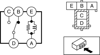
-
If it can be verified, replace the relay. (See RELAY LOCATION.)
-
If it cannot be verified, go to the next step.
3. Verify the continuity between the relay terminals E and A.
-
If it can be verified, go to the next step.
-
If it cannot be verified, replace the relay. (See RELAY LOCATION.)
4. Verify the continuity between the relay terminals B and D.
-
If it can be verified, go to the next step.
-
If it cannot be verified, replace the relay. (See RELAY LOCATION.)
5. Apply battery voltage to relay terminal E, and connect terminal A to ground.
6. Verify the continuity between relay terminals C and D.
-
If it cannot be verified, replace the relay. (See RELAY LOCATION.)
Type C
1. Remove the relay. (See RELAY LOCATION.)
2. Verify the continuity between the relay terminals C and A.
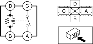
-
If it can be verified, replace the relay. (See RELAY LOCATION.)
-
If it cannot be verified, go to the next step.
3. Verify the continuity between the relay terminals D and B.
-
If it can be verified, go to the next step.
-
If it cannot be verified, replace the relay. (See RELAY LOCATION.)
4. Apply battery voltage to relay terminal D, and connect terminal B to ground.
5. Verify the continuity between relay terminals C and A.
-
If it cannot be verified, replace the relay. (See RELAY LOCATION.)