CONTROL VALVE BODY INSTALLATION [SJ6A-EL]
2016 – MX-5 – Transmission/Transaxle
CONTROL VALVE BODY INSTALLATION [SJ6A-EL]
On-Vehicle Installation
CAUTION:
-
When installing the control valve body component, do not put the coupler component in the open space of the separate plate in the control valve body component.
-
Do not pinch the coupler component between the separate plate and the control valve body component.
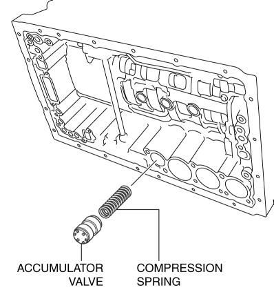
1. Install the accumulator valve and compression springs to the transmission case.
CAUTION:
-
Do not to damage the O-ring and accumulator piston.
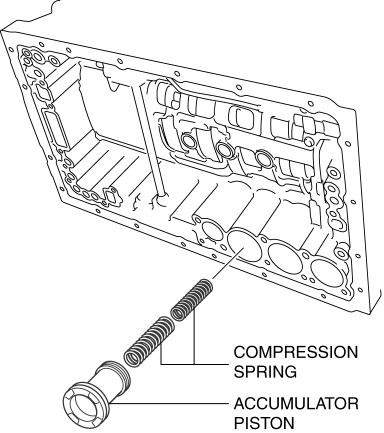
2. Coat the new O-rings with ATF, and install it to the accumulator piston (C-3).
3. Install the accumulator piston (C-3) and the compression spring to the transmission case.
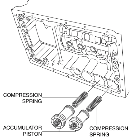
4. Coat the new O-rings with ATF, and install it to the accumulator pistons (C-2, B-3).
5. Install the compression springs and the snap rings to the accumulator pistons (C-2, B-3) using a flathead screwdriver.
6. Install the accumulator pistons (C-2, B-3) and the compression springs to the transmission case.
CAUTION:
-
Do not to damage the gasket.
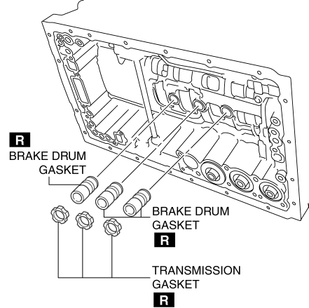
7. Coat the new transmission gaskets and the new brake drum gaskets with ATF, and install them to the transmission case.
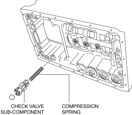
8. Install the check valve sub-component and the compression spring to the transmission case.
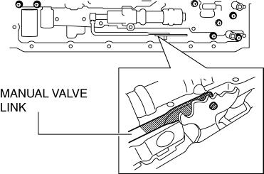
9. Connect the manual valve link and install the control valve body component.
CAUTION:
-
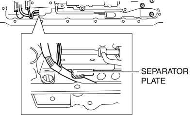
When installing, always put the wiring harness in the concave portion of the separator plate in the control valve body component as shown in the figure.
10. Temporarily install the control valve body component with the bolts.

-
Bolt length (measured from below the head)
-
A: 25 mm {0.98 in}
-
B: 36 mm {1.4 in}
-
C: 45 mm {1.8 in}
-
D: 50 mm {2.0 in}
NOTE:
-
Align with the bolt holes and temporarily tighten the bolts by hand.
-
Tighten the bolts starting from the inner ones and moving in a criss-cross pattern.
11. Tighten the bolts.
-
Tightening torque
-
10—12 N·m {102—122 kgf·cm, 89—106 in·lbf}
12. Install the detent spring cover and detent spring with the bolt to the control valve body component.
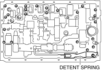
-
Tightening torque
-
8—12 N·m {82—122 kgf·cm, 71—106 in·lbf}
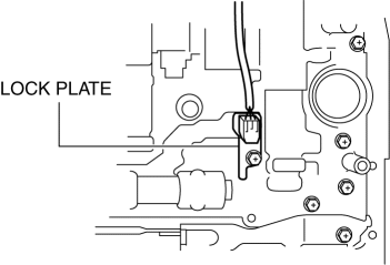
13. Install the TFT sensor and the lock plate with the bolt to the control valve body component.
-
Tightening torque
-
8—12 N·m {82—122 kgf·cm, 71—106 in·lbf}
14. Connect the coupler component to the clamps.
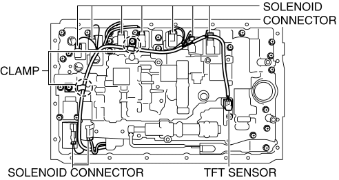
15. Connect the connectors to the solenoids.
16. Coat a new O-ring with ATF and install it to the oil strainer.
17. Install the oil strainer with the bolts to the control valve body component.
-
Tightening torque
-
8—12 N·m {82—122 kgf·cm, 71—106 in·lbf}
CAUTION:
-
Be careful not to allow foreign matter to penetrate the interior of the transmission.
18. Clean the contact surface of oil pan and transmission case.
NOTE:
-
Clean the oil cleaner magnets before installing them.
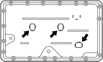
19. Install the magnets to the oil pan.
CAUTION:
-
Do not to damage the contact surface of the transmission case and the oil pan.
-
Do not to deform the oil pan.
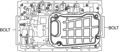
20. Install a new oil pan gasket and the oil pan to the transmission case.
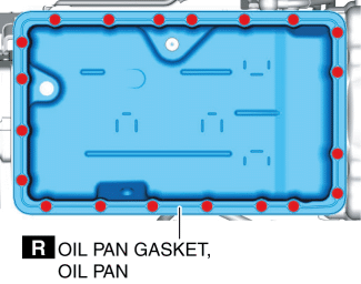
CAUTION:
-
Be careful not to tighten the bolts excessively because the oil pan gasket is made of cork.
21. Install the bolts to the transmission case.
-
Tightening torque
-
6.0—7.9 N·m {62—80 kgf·cm, 54—69 in·lbf}
22. Connect the negative battery cable. (See NEGATIVE BATTERY CABLE DISCONNECTION/CONNECTION.)
23. Add ATF and, with the engine idling, inspect the ATF level and for leakage. (See AUTOMATIC TRANSMISSION FLUID (ATF) LEVEL ADJUSTMENT [SJ6A-EL].)
24. Perform the mechanical system test. (See MECHANICAL SYSTEM TEST [SJ6A-EL].)
25. Perform the road test. (See ROAD TEST [SJ6A-EL].)