Menu +
Generic selectors
Exact matches only
Search in title
Search in content
Post Type Selectors

DTC U3003:16/U3003:17/U3003:1E [DSC HU/CM]

< Previous Next >

2016 – MX-5 – Brakes

DTC U3003:16/U3003:17/U3003:1E [DSC HU/CM]

DTC

U3003:16

Power supply

U3003:17

U3003:1E

DETECTION CONDITION

  • Power supply malfunction is detected.

FAIL-SAFE FUNCTION

POSSIBLE CAUSE

  • DTC is stored in PCM

  • Battery malfunction

  • Generator malfunction

  • Fuse (SRS1 7.5A, ABS/DSC S 30A, ABS/DSC M 50A) malfunction

  • Short to ground or open circuit in wiring harness between battery and DSC HU/CM terminal I

  • Short to ground or open circuit in wiring harness between battery and DSC HU/CM terminal A

  • Short to ground or open circuit in wiring harness between battery and DSC HU/CM terminal B

  • Open circuit in wiring harness between DSC HU/CM terminal AK and body ground

  • Poor connection at each connector

  • DSC HU/CM malfunction

Diagnostic Procedure

Step

Inspection

Action

1

VERIFY PCM DTC

Yes

Go to the applicable DTC inspection.

(See DTC TABLE [PCM (SKYACTIV-G 2.0)].)

DTC troubleshooting completed, then go to the next step.

No

Go to the next step.

2

INSPECT BATTERY

Yes

Charge or replace the battery, then go to Step7.

(See BATTERY RECHARGING.)

(See BATTERY REMOVAL/INSTALLATION [SKYACTIV-G 2.0].)

No

Go to the next step.

3

INSPECT GENERATOR

Yes

Replace the generator, then go to Step7.

(See GENERATOR REMOVAL/INSTALLATION [SKYACTIV-G 2.0].)

No

Go to the next step.

4

INSPECT FUSE CONDITION

  • Is the fuse (SRS1 7.5A, ABS/DSC S 30A, ABS/DSC M 50A) normal?

Yes

Go to the next step.

No

  • If the fuse is blown:

    • Refer to the wiring diagram and verify whether or not there is a common connector between fuse and DSC HU/CM terminal I, A and B.

      • If there is a common connector:

      • Determine the malfunctioning part by inspecting the common connector and the terminal for corrosion, damage, or pin disconnection, and the common wiring harness for a short to ground.

      • Repair or replace the malfunctioning part.

        If there is no common connector:

      • Repair or replace the wiring harness which has a short to ground.

      • Replace the fuse.

  • If the fuse is damaged:

    • Replace the fuse.

Go to Step7.

5

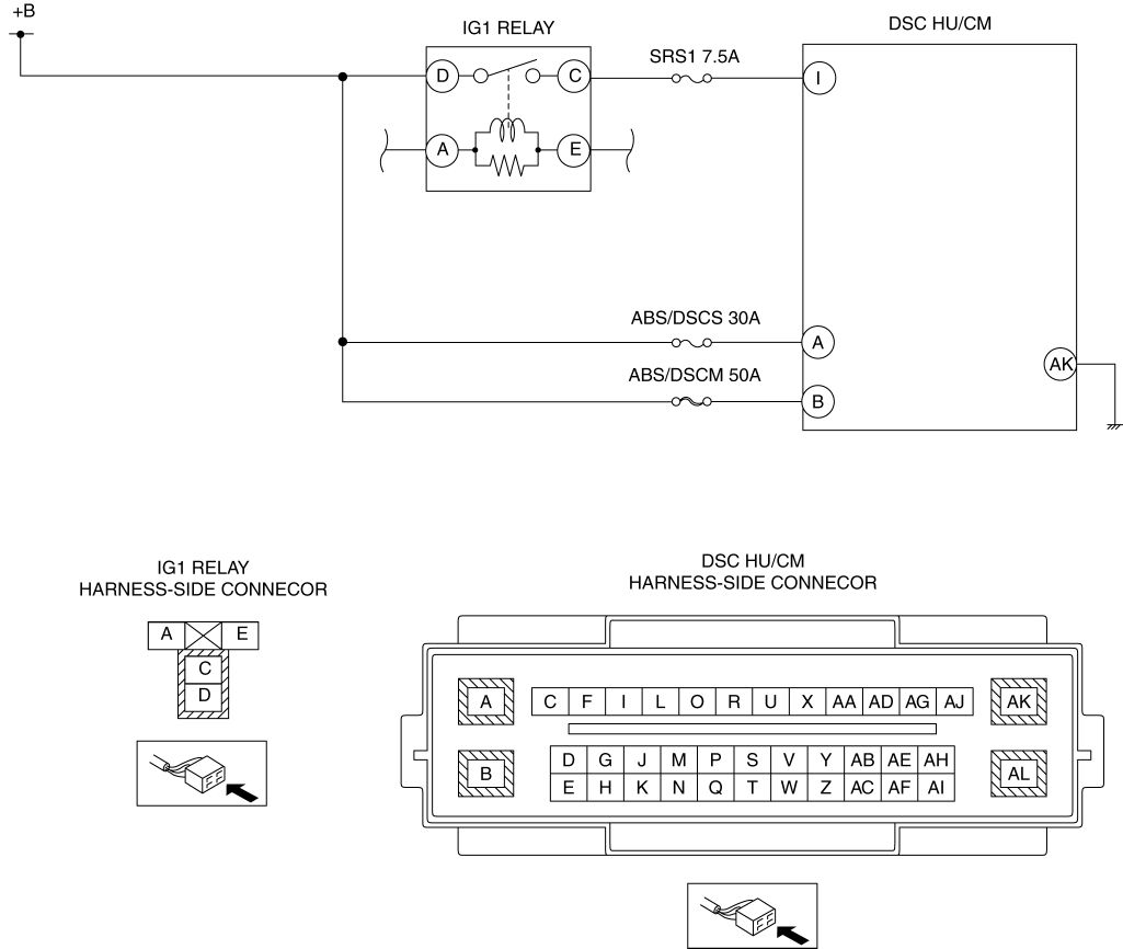
INSPECT DSC HU/CM POWER CIRCUIT FOR OPEN CIRCUIT

  • Switch the ignition OFF.

  • Disconnect the DSC HU/CM connector.

  • Switch the ignition ON (engine off).

  • Measure the voltage as followings:

    • DSC HU/CM terminal I (wiring harness-side)—body ground

    • DSC HU/CM terminal A (wiring harness-side)—body ground

    • DSC HU/CM terminal B (wiring harness-side)—body ground

  • Is the voltage 10 V or more?

Yes

Go to the next Step.

No

Refer to the wiring diagram and verify whether or not there is a common connector in the followings.

  • Battery—DSC HU/CM terminal I

  • Battery—DSC HU/CM terminal A

  • Battery—DSC HU/CM terminal B

    If there is a common connector:

  • Determine the malfunctioning part by inspecting the common connector and the terminal for corrosion, damage, or pin disconnection, and the common wiring harness for an open circuit.

  • Repair or replace the malfunctioning part.

    If there is no common connector:

  • Repair or replace the wiring harness which has an open circuit.

Go to Step7.

6

INSPECT DSC HU/CM GROUND CIRCUIT FOR OPEN CIRCUIT OR POOR GROUND

  • Switch the ignition OFF.

  • Disconnect the DSC HU/CM connector.

  • Measure the resistance between DSC HU/CM terminal AK (wiring harness-side) and body ground.

  • Is the resistance 0—1 ohm?

Yes

Go to the next step.

No

  • If the open circuit could be detected in the wiring harness:

    • Refer to the wiring diagram and verify whether or not there is a common connector between DSC HU/CM terminal AK and body ground.

      • If there is a common connector:

      • Determine the malfunctioning part by inspecting the common connector and the terminal for corrosion, damage, or pin disconnection, and the common wiring harness for an open circuit.

      • Repair or replace the malfunctioning part.

        If there is no common connector:

      • Repair or replace the wiring harness which has an open circuit.

    • Go to the next step.

  • If the resistance is out of specification:

    • Refer to the wiring diagram and verify whether or not there is a common connector between DSC HU/CM terminal AK and body ground.

      • If there is a common connector:

      • Determine the malfunctioning part by inspecting the common connector and the terminal for corrosion, damage, or pin disconnection, and the common wiring harness for a poor ground.

      • Repair or replace the malfunctioning part.

        If there is no common connector:

      • Repair or replace the wiring harness which has a poor ground.

    • Go to the next step.

7

VERIFY DTC TROUBLESHOOTING COMPLETED

Yes

Repeat the inspection from Step1

If the malfunction recurs, replace the DSC HU/CM, then go to the next step.

(See DSC HU/CM REMOVAL/INSTALLATION.)

No

Go to the next step.

8

VERIFY NO DTC IS PRESENT

  • Are any DTCs present?

Yes

Go to the applicable DTC inspection.

(See DTC TABLE [DSC HU/CM].)

No

DTC troubleshooting completed.

< Previous Next >

© 2014 Mazda North American Operations, U.S.A.