DSC HU/CM REMOVAL/INSTALLATION
2016 – MX-5 – Brakes
DSC HU/CM REMOVAL/INSTALLATION
WARNING:
-
If the DSC HU/CM configuration is not completed, it could result in an unexpected accident due to the DSC being inoperative. If the DSC HU/CM is replaced, always use the automatic configuration function so that the DSC operation conditions are correct.
-
If the DSC related parts sensor initialization procedure is not completed, the DSC will not operate properly and it might cause an unexpected accident. Therefore, after replacing the DSC HU/CM, always perform the DSC related parts sensor initialization procedure to insure proper DSC operation.
CAUTION:
-
The internal parts of the DSC HU/CM could be damaged if dropped. Be careful not to drop the DSC HU/CM. Replace the DSC HU/CM if it is subjected to an impact.
NOTE:
-
When the ignition is switched ON (engine off or on) after the DSC HU/CM is replaced, the DSC HU/CM reads the vehicle specification information sent via CAN communication from the instrument cluster and stores it.
-
The DSC HU/CM prior to replacement stores the vehicle specification information.
-
A new DSC HU/CM does not store any vehicle specification information.
1. Disconnect the negative battery cable. (See NEGATIVE BATTERY CABLE DISCONNECTION/CONNECTION.)
2. Remove in the order indicated in the table.
3. Install in the reverse order of removal.
4. After installation, add brake fluid, bleed the air, and inspect for fluid leakage. (See BRAKE FLUID AIR BLEEDING.)
5. If the DSC HU/CM is replaced, perform the auto configuration and the initialization of the sensors for DSC-related parts.
a. Switch the ignition ON (engine off or on) and wait for 10 s or more.
b. Switch the ignition off and wait for 3 s or more.
c. Switch the ignition ON (engine off or on) and wait for 3 s or more for the DSC HU/CM auto configuration to complete.
d. Clear the DTC. (See CLEARING DTC [DSC HU/CM].)
e. Switch the ignition off and wait for 3 s or more.
f. Switch the ignition ON (engine off or on) and wait for 10 s or more.
g. Using the M-MDS, verify that DTCs U2300:54/U2300:55/U2300:56/U2300:64 are not displayed.
-
If DTCs U2300:54/U2300:55/U2300:56/U2300:64 are displayed, go to the DTC troubleshooting procedure. (See DTC U2300:54/U2300:55/U2300:56/U2300:64 [DSC HU/CM].)
h. Perform the sensor initialization for the DSC-related parts. (See DSC RELATED PARTS SENSOR INITIALIZATION PROCEDURE.)
i. Clear the DTC. (See CLEARING DTC [DSC HU/CM].)
j. Switch the ignition off and wait for 3 s or more.
k. Switch the ignition ON (engine off or on) and wait for 10 s or more.
l. Using the M-MDS, verify that DTCs C0044:54/C0061:54/C0062:54/C0063:54 are not displayed.
-
If DTCs C0044:54/C0061:54/C0062:54/C0063:54 are displayed, go to the DTC troubleshooting procedure. (See DTC C0044:01/C0044:28/C0044:49/C0044:54 [DSC HU/CM].) (See DTC C0061:28/C0061:54/C0061:64 [DSC HU/CM].) (See DTC C0062:28/C0062:54/C0062:64 [DSC HU/CM].) (See DTC C0063:28/C0063:54/C0063:64 [DSC HU/CM].)
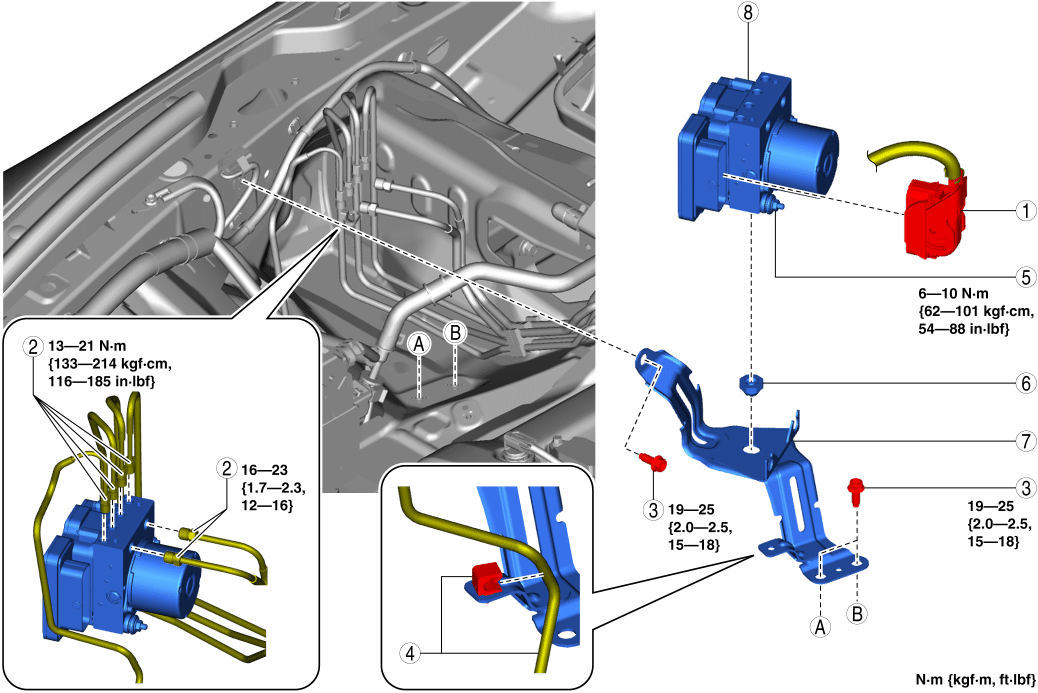
|
1 |
DSC HU/CM Connector |
|
2 |
Brake pipe (See Brake Pipe Removal Note.) (See Brake Pipe Installation Note.) |
|
3 |
Bolt (See Bolt Installation Note.) |
|
4 |
Clip, Brake pipe |
|
5 |
Nut |
|
6 |
Mount rubber |
|
7 |
Bracket |
|
8 |
DSC HU/CM |
DSC HU/CM Connector Removal Note
CAUTION:
-
If sand or other particles get into the connector, it may be difficult to remove. To prevent damaging the connector, be careful not to use excessive force when disconnecting it.
1. Pull the lock lever down in the direction of the arrow while pressing the tab of the lock lever.
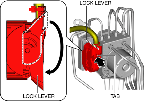
2. Disconnect the DSC HU/CM connector.
Brake Pipe Removal Note
1. Place an alignment marks on the brake pipe and DSC HU/CM.
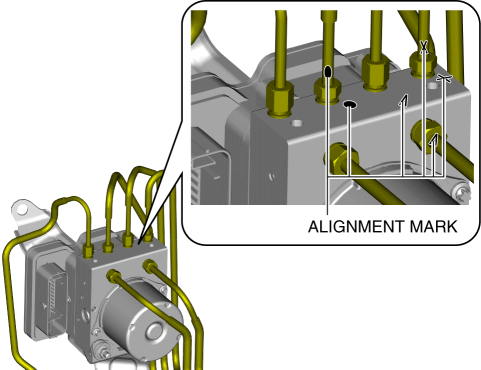
2. Apply protective tape to the connector to prevent brake fluid from entering.
3. Disconnect the brake pipes.
Clip, Brake Pipe Installation Note
1. Install the clip as shown in the figure.
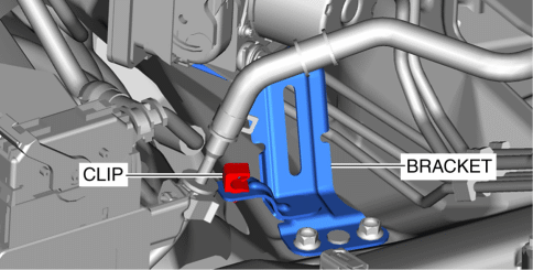
2. Install the brake pipe to the clip.
Bolt Installation Note
1. Tighten the bolt A to the specified torque.
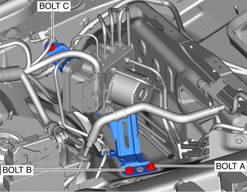
-
Tightening torque
-
19???25 N·m {2.0???2.5 kgf·m, 15???18 ft·lbf}
2. Tighten the bolt B to the specified torque.
-
Tightening torque
-
19???25 N·m {2.0???2.5 kgf·m, 15???18 ft·lbf}
3. Tighten the bolt C to the specified torque.
-
Tightening torque
-
19???25 N·m {2.0???2.5 kgf·m, 15???18 ft·lbf}
Brake Pipe Installation Note
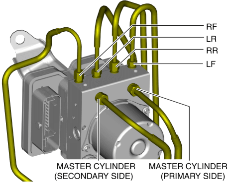
1. Align the marks made before removal and install the brake pipe to the DSC HU/CM and brake pipe joint referring to the figure.
DSC HU/CM Connector Installation Note
1. Connect the connector and pull the lock lever up in the direction of the arrow.
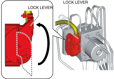
2. After connecting the connector, verify that the connector cover is completely pushed in.