REAR STABILIZER REMOVAL/INSTALLATION
2016 – MX-5 – Suspension
REAR STABILIZER REMOVAL/INSTALLATION
CAUTION:
-
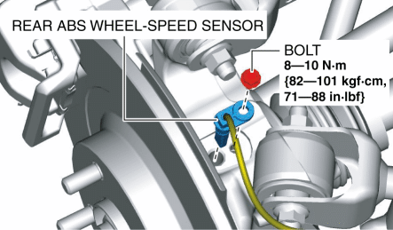
Performing the following procedures could cause an open circuit in the rear ABS wheel-speed sensor wiring harness if it is pulled by mistake. Before servicing, disconnect the rear ABS wheel-speed sensor and set it aside so that the wiring harness will not be pulled by mistake.
1. Remove the rear ABS wheel-speed sensor from the hub support.
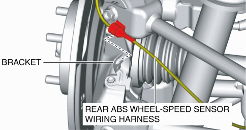
2. Remove the rear ABS wheel-speed sensor wiring harness from the bracket and set it aside so that it does not interfere with the servicing.
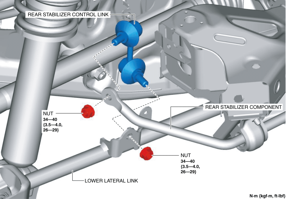
3. Remove the rear stabilizer control link.
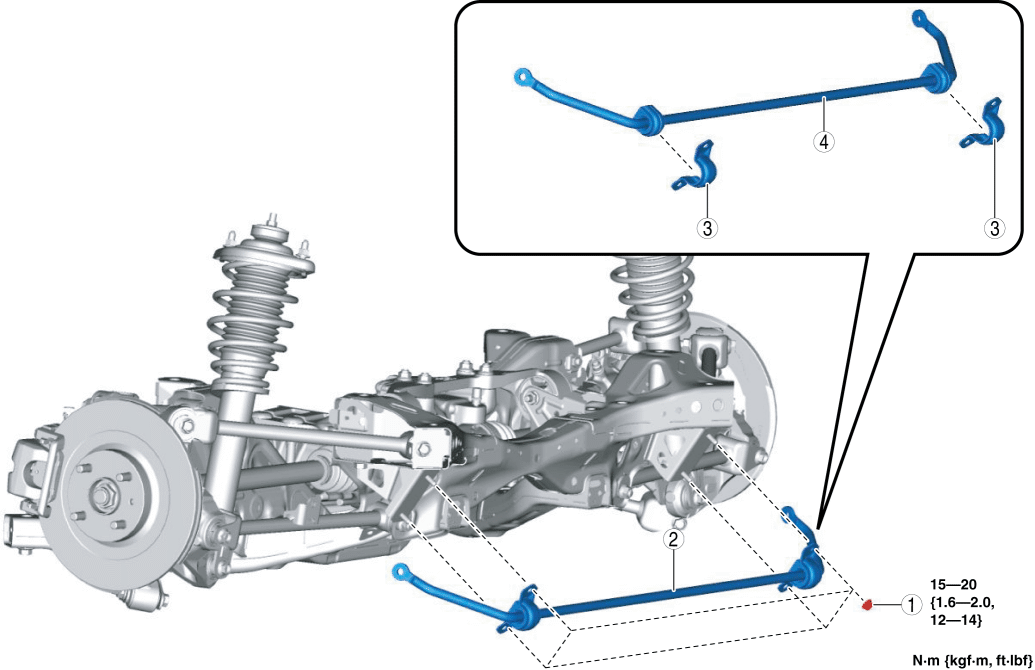
4. Remove in the order indicated in the table.
5. Install in the reverse order of removal.
|
1 |
Nut (See Nut Installation Note.) |
|
2 |
Rear stabilizer component |
|
3 |
Rear stabilizer bracket |
|
4 |
Rear stabilizer |
Rear Stabilizer Bracket Removal Note
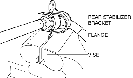
1. If the rear stabilizer bracket cannot be removed by hand, remove it using a vise.
CAUTION:
-
The rear stabilizer bracket may be deformed if it is removed using a vise. When removing the rear stabilizer bracket using a vise, secure the rear stabilizer bracket flange to the vise as shown in the figure, then remove it.
Rear Stabilizer Bracket Installation Note
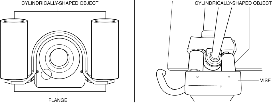
1. If the rear stabilizer bracket cannot be installed by hand, install it using a vise.
CAUTION:
-
The rear stabilizer bracket may be deformed if it is installed using a vise. When installing the rear stabilizer bracket using a vise, set the cylinder-shaped parts as shown in the figure so that pressure is applied to the rear stabilizer bracket flange, and install the rear stabilizer bracket to the rear stabilizer bushing.
2. After installing the rear stabilizer bracket, verify that the positions of the rear stabilizer bracket and the rear stabilizer bushing are within the range shown in the figure.
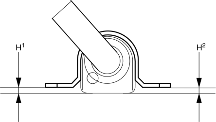
-
H1: 6.5 mm {0.26 in} max.
-
H2: 6.5 mm {0.26 in} max.
Rear Stabilizer Component Installation Note
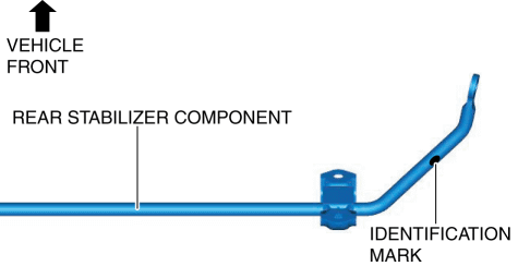
1. Assembly the rear stabilizer component so that the identification mark is on the right side of the vehicle.
Nut Installation Note
1. Temporarily install nut A and B.
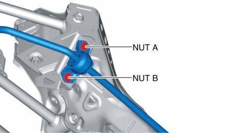
2. Tighten bolt B.
-
Tightening torque
-
15???20 N·m {1.6???2.0 kgf·m, 12???14 ft·lbf}
3. Tighten bolt A.
-
Tightening torque
-
15???20 N·m {1.6???2.0 kgf·m, 12???14 ft·lbf}
4. Tighten bolt B.
-
Tightening torque
-
15???20 N·m {1.6???2.0 kgf·m, 12???14 ft·lbf}