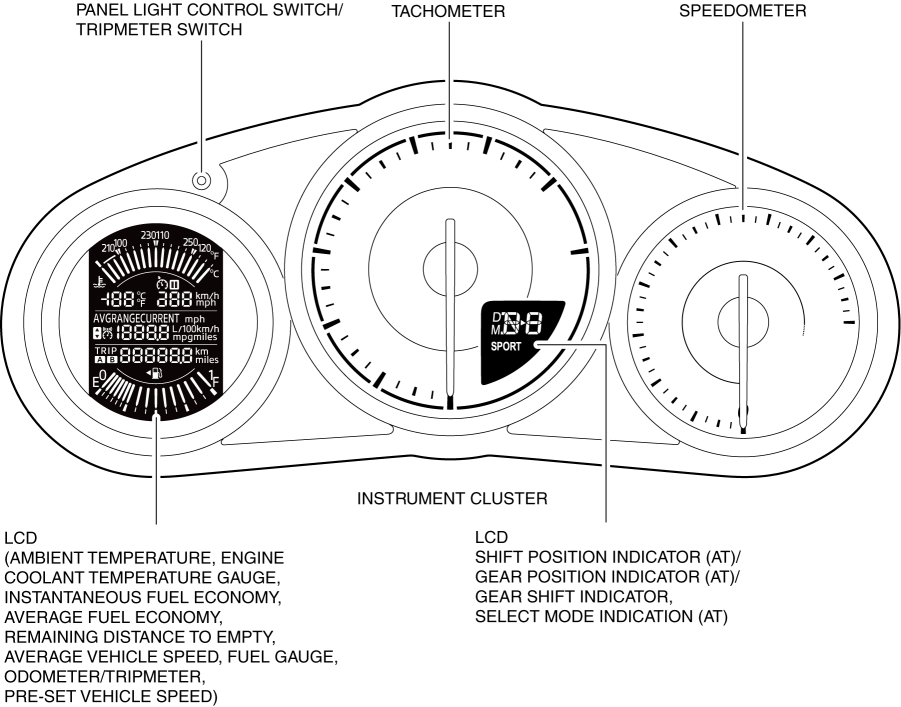
INSTRUMENT CLUSTER
2016 – MX-5 – Body and Accessories
INSTRUMENT CLUSTER
Outline
-
The instrument cluster centrally controls the following:
-
Warning beep
-
Warning light/Indicator light
-
Analog speedometer
-
Analog tachometer
-
Fuel gauge
-
Odometer/tripmeter
-
Panel light
-
Trip computer system
-
LCD
-
Engine coolant temperature gauge
-
Ambient temperature display
Functions
-
The instrument cluster displays the following information to notify the driver of the vehicle conditions.
-
Vehicle speed (speedometer display function)
-
Engine speed (tachometer display function)
-
Remaining fuel quantity (fuel gauge display function)
-
Traveled distance (odometer/tripmeter display function)
-
Instantaneous fuel economy, average fuel economy, remaining distance to empty, average vehicle speed (trip computer calculation function)
-
Warning/indicator light (warning/indicator light turn on/flash function)
Speedometer display function
-
The instrument cluster controls the speedometer based on the vehicle speed signal sent via CAN communication from the PCM, and displays the current vehicle speed. For details on the speedometer, refer to [SPEEDOMETER]. (See SPEEDOMETER.)
Tachometer display function
-
The instrument cluster controls the tachometer based on the engine speed signal sent via CAN communication from the PCM, and displays the current engine speed. For details on the tachometer, refer to [TACHOMETER]. (See TACHOMETER.)
Fuel gauge display function
-
The instrument cluster displays the remaining fuel quantity based on the fuel gauge sender unit voltage signal sent via CAN communication from the BCM, and the vehicle speed and fuel injection amount signals sent via CAN communication from the PCM. For details on the remaining fuel quantity, refer to [FUEL GAUGE]. (See FUEL GAUGE.)
Odometer/tripmeter display function
-
The instrument cluster displays the total traveled distance/traveled distance over a specific interval based on the travel distance signal sent via CAN communication from the PCM. For details on the odometer/tripmeter, refer to [ODOMETER/TRIPMETER]. (See ODOMETER/TRIPMETER.)
Trip computer calculation function
-
The instrument cluster calculates the instantaneous fuel economy, average fuel economy, remaining distance to empty, and the average vehicle speed, and displays it on the LCD in the instrument cluster. For details on the trip computer, refer to [TRIP COMPUTER INFORMATION SYSTEM]. (See TRIP COMPUTER INFORMATION SYSTEM.)
Warning/indicator light turn on/flash function, message/system operation status display function
-
The instrument cluster turns on or flashes the warning indicator lights to notify the driver of the vehicle system status.
-
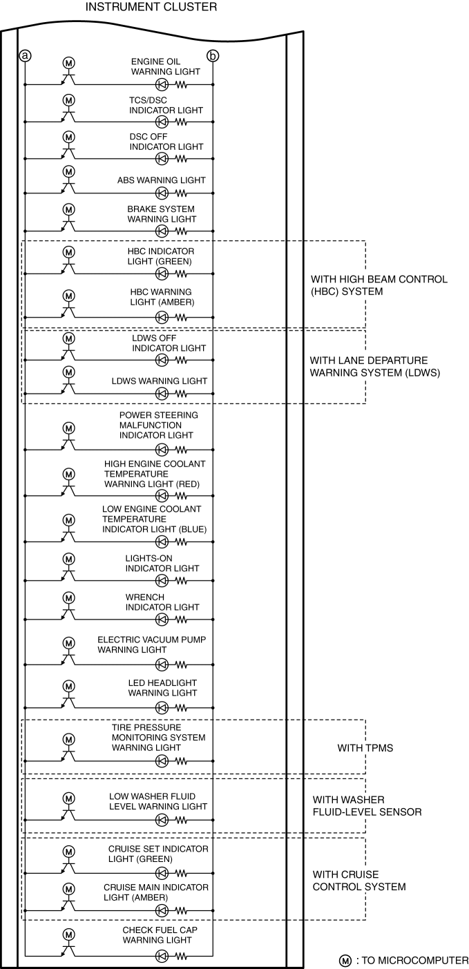
The types of warning/indicator lights are as follows: For details on each warning/indicator light, refer to each reference.
-
For vehicles with the center display, a warning message in the center display is displayed when the warning/indicator light is turned on or flashed. For the display content, refer to [CENTER DISPLAY]. (See CENTER DISPLAY [WITH CENTER DISPLAY].)
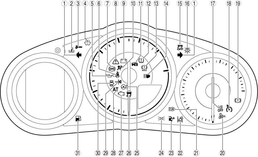
×: Applicable—: Not applicable
|
No. |
Warning light/Indicator light |
Name |
Message is displayed in center display when warning/indicator light turns on/flashes |
Comment |
Warning/indicator light turned on when ignition is switched ON (engine off or on) |
Reference |
|
1 |
|
Turn signal/hazard warning indicator lights |
— |
— |
— |
|
|
2 |
|
Low engine coolant temperature indicator light (blue)/high engine coolant temperature warning light (red) |
× |
— |
× |
|
|
3 |
|
Wrench indicator light |
— |
— |
× |
|
|
4 |
|
Low washer fluid level warning light |
× |
With washer fluid-level sensor |
— |
|
|
5 |
|
Engine oil warning light |
× |
— |
× |
|
|
6 |
|
Seat belt warning light |
— |
— |
— |
(See SEAT BELT WARNING LIGHT.) |
|
7 |
|
ABS warning light |
× |
— |
× |
(See BRAKE WARNING LIGHT/ABS WARNING LIGHT/ELECTRIC VACUUM PUMP WARNING LIGHT.) |
|
8 |
|
Master warning light |
× |
— |
× |
(See MASTER WARNING LIGHT.) |
|
9 |
|
Charging system warning light |
— |
— |
× |
|
|
10 |
|
Air bag/seat belt pretensioner system warning light |
× |
— |
× |
(See AIR BAG/SEAT BELT PRE-TENSIONER SYSTEM WARNING LIGHT [TWO-STEP DEPLOYMENT CONTROL SYSTEM].) (See AIR BAG/SEAT BELT PRE-TENSIONER SYSTEM WARNING LIGHT [STANDARD DEPLOYMENT CONTROL SYSTEM].) |
|
11 |
|
Security indicator light |
— |
— |
× |
(See SECURITY INDICATOR LIGHT.) |
|
12 |
|
Tire pressure monitoring system warning light |
× |
With TPMS |
× |
|
|
13 |
|
Brake system warning light |
× |
— |
× |
(See BRAKE WARNING LIGHT/ABS WARNING LIGHT/ELECTRIC VACUUM PUMP WARNING LIGHT.) |
|
14 |
|
Headlight high-beam indicator light |
— |
— |
— |
|
|
15 |
|
DSC OFF indicator light |
— |
— |
× |
|
|
16 |
|
LED headlight warning light |
× |
— |
× |
(See LED HEADLIGHT WARNING LIGHT.) |
|
17 |
|
LDWS OFF indicator light |
— |
With lane departure warning system (LDWS) |
× |
(See LDWS OFF INDICATOR LIGHT.) |
|
18 |
|
Cruise main indicator light (amber)/cruise set indicator light (green) |
— |
With cruise control system |
— |
(See CRUISE MAIN INDICATOR LIGHT (AMBER), CRUISE SET INDICATOR LIGHT (GREEN) [SKYACTIV-G 2.0].) |
|
19 |
|
Electric vacuum pump warning light |
— |
— |
× |
(See BRAKE WARNING LIGHT/ABS WARNING LIGHT/ELECTRIC VACUUM PUMP WARNING LIGHT.) |
|
20 |
|
Blind spot monitoring (BSM) OFF indicator light |
— |
With blind spot monitoring (BSM) system |
× |
|
|
21 |
|
HBC indicator light (green)/HBC warning light (amber) |
× |
With high beam control (HBC) system |
× |
(See HBC INDICATOR LIGHT (GREEN)/HBC WARNING LIGHT (AMBER).) |
|
22 |
|
LDWS warning light |
× |
With lane departure warning system (LDWS) |
× |
(See LDWS WARNING LIGHT.) |
|
23 |
|
Check fuel cap warning light |
× |
— |
× |
|
|
24 |
|
Lights-on indicator light |
— |
— |
— |
(See LIGHTS-ON INDICATOR LIGHT.) |
|
25 |
|
Power steering malfunction indicator light |
× |
— |
× |
|
|
26 |
|
TCS/DSC indicator light |
× |
— |
× |
(See TCS/DSC INDICATOR LIGHT.) |
|
27 |
|
Check engine light |
× |
— |
× |
|
|
28 |
|
Automatic transmission warning light |
× |
AT |
× |
|
|
29 |
|
KEY warning light (red)/KEY indicator light (green) |
× |
— |
× |
|
|
30 |
|
Door-ajar warning light |
— |
— |
— |
(See DOOR-AJAR WARNING LIGHT.) |
|
31 |
|
Low fuel warning light |
× |
— |
— |
(See LOW FUEL WARNING LIGHT.) |


Buzzer operation function
-
The instrument cluster activates the alarm using the buzzer built into the instrument cluster to notify the driver of the vehicle conditions.
-
The alarm types are as follows: For details on each alarm, refer to each reference.
|
Name |
Reference |
|
Lights-on reminder warning alarm |
|
|
Seat belt warning alarm |
(See SEAT BELT WARNING ALARM.) |
|
Keyless warning alarm |
(See KEYLESS WARNING ALARM.) |
|
Air bag system warning alarm |
(See AIR BAG SYSTEM WARNING ALARM [TWO-STEP DEPLOYMENT CONTROL SYSTEM].) (See AIR BAG SYSTEM WARNING ALARM [STANDARD DEPLOYMENT CONTROL SYSTEM].) |
|
Blind spot monitoring (BSM) warning buzzer (with blind spot monitoring (BSM) system) |
|
|
Lane departure warning sound (with lane departure warning system (LDWS)) |
(See LANE DEPARTURE WARNING SOUND.) |
|
Turn and hazard indicator alarm |
|
|
Tire pressure monitoring system warning alarm (with TPMS) |
|
|
Panel light control indicator alarm |
-
If several alarm request signals are received simultaneously, the alarms sound according to the order of precedence in the following table.
With ignition switched off
|
Order of precedence |
Name |
|
1 |
Keyless warning alarm (pattern A, B) |
|
2 |
Lights-on reminder warning alarm |
|
3 |
Turn and hazard indicator alarm |
|
4 |
Panel light control indicator alarm |
With ignition switched ON (engine off or on)
|
Order of precedence |
Name |
|
1 |
Blind spot monitoring (BSM) warning buzzer (rear cross traffic alert (RCTA) function) |
|
2 |
Seat belt warning alarm |
|
3 |
Tire pressure monitoring system warning alarm |
|
4 |
Blind spot monitoring (BSM) warning buzzer (blind spot monitoring (BSM) function) |
|
5 |
Lane departure warning sound |
|
6 |
Keyless warning alarm |
|
7 |
Air bag system warning alarm |
|
8 |
Turn and hazard indicator alarm |
|
9 |
Panel light control alarm |
Panel Light Control Function
-
The instrument cluster changes the brightness of the panel light based on the panel light control switch rotation signal and TNS (parking lights) signal sent via CAN communication from the BCM. For details on the panel light, refer to [PANEL LIGHT]. (See PANEL LIGHT.)
Vehicle Specification Information Transmission Function
-
The instrument cluster sends vehicle specification information stored during configuration to the following modules via CAN communication. The following modules perform configuration automatically by reading the vehicle specification information from the instrument cluster.
-
PCM
-
TCM (AT)
-
Auto leveling control module (without adaptive front lighting system (AFS))
-
AFS control module (with adaptive front lighting system (AFS))
-
DSC HU/CM
-
Electric vacuum pump control unit
-
EPS control module
-
BCM
-
Start stop unit
-
SAS control module
-
Connectivity master unit (CMU) (with center display)
-
Audio amplifier (with Bose®)
-
Climate control unit
-
Blind spot monitoring (BSM) control module (with blind spot monitoring (BSM) system)
Battery Discharge Suppression Function
NOTE:
-
This function is for suppressing battery discharge during vehicle manufacture and shipment. However, if the ROOM fuse is removed from a vehicle which has low total travel distance, the function may operate in the market.
-
The battery discharge suppression is a function in which the instrument cluster sends a battery discharge suppression signal to the start stop unit and the start stop unit suppresses the battery discharge.
-
The battery discharge suppression function operates when the total traveled distance is the threshold or less and the ROOM fuse has been removed.
-
The start stop unit switches the ignition off if 25 min have elapsed with the ignition switch in the ACC or ON position (engine off) to control the electric load.
-
When the battery discharge suppression function is operated, the instrument cluster displays [F0-002], [F0-HHH] or [F0-LLL] in the odometer/tripmeter screen of the instrument cluster to indicate that the battery discharge suppression function is operating.
-
The battery discharge suppression function is stopped under the following conditions.
-
ROOM fuse has been installed
-
Engine is started
-
Total traveled distance exceeds the threshold value
Structural View
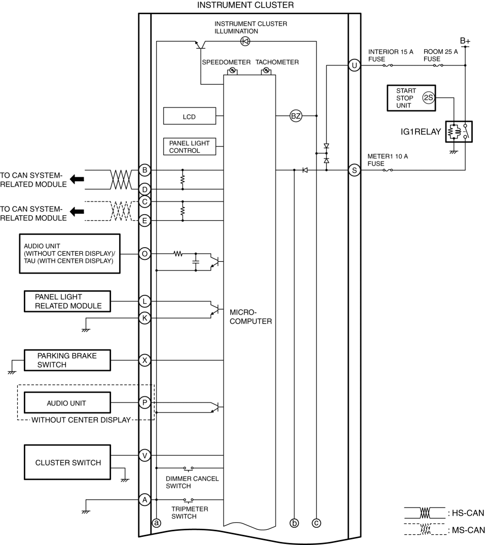
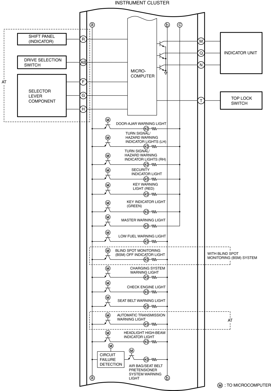
System Wiring Diagram
Fail-safe
Speedometer
-
If the instrument cluster cannot receive a CAN signal normally or detects a CPU malfunction inside the instrument cluster, 0 is displayed.
Tachometer
-
If the instrument cluster cannot receive a CAN signal normally or detects a CPU malfunction inside the instrument cluster, 0 is displayed.
Fuel gauge
-
Not applicable
Odometer/tripmeter
-
If the instrument cluster detects a CPU malfunction inside the instrument cluster, [— — — — — —] is displayed.
Engine coolant temperature gauge
-
If the instrument cluster cannot receive a CAN signal normally, it turns off the low engine coolant temperature indicator light (blue) and turns on the high engine coolant temperature warning light (red).
-
If the instrument cluster detects a CPU malfunction inside the instrument cluster, it turns on the high engine coolant temperature warning light (red).
Indicator light
-
If the instrument cluster cannot receive a CAN signal normally, it flashes the following indicator lights.
-
Lights-on indicator light
-
Wrench indicator light
Warning lights
-
If the instrument cluster cannot receive a CAN signal normally, it turns the following warning lights on.
-
High engine coolant temperature warning light (red)
-
HBC warning light (amber)
-
Master warning light
-
LED headlight warning light
-
Check engine light
-
Brake system warning light
-
Engine oil warning light
-
KEY warning light (red)
-
LDWS warning light
-
ABS warning light
-
Power steering malfunction indicator light
-
Charging system warning light
-
Electric vacuum pump warning light
-
Tire pressure monitoring system warning light
-
Low washer fluid level warning light
Alarm
-
If the instrument cluster cannot receive a CAN signal normally, it stops the alarm.
Panel light
-
If the instrument cluster cannot receive a CAN signal normally, it stops sending the dimmer cancel signal.
Trip computer
-
If the instrument cluster cannot receive a CAN signal normally or detects a configuration malfunction, [———] is displayed.
Ambient temperature display
-
If the CAN signal cannot be received normally, the instrument cluster displays [———°C] or [———°F].
-
If the instrument cluster detects a CPU malfunction inside the instrument cluster, [———] is displayed.