MULTIPLEX COMMUNICATION SYSTEM
2016 – MX-5 – Multiplex Communication System
MULTIPLEX COMMUNICATION SYSTEM
Outline
-
A control area network (CAN) system has been adopted in which the multiple control modules send/receive signals using two common communication lines.
-
Local CAN, ISO communication, or LIN communication has been adopted for the individual communication between control modules in consideration of the communication speed and the cost.
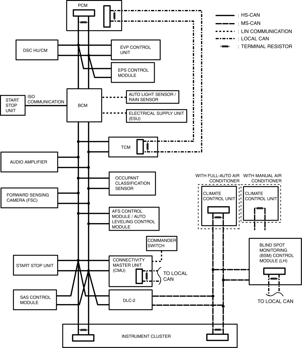
System Wiring Diagram
NOTE:
-
The following figure shows the CAN/LIM communication/ISO communication/local CAN connection conditions. Availability depends on the vehicle specification.
CAN/LIN communication/ISO communication
Local CAN
Structural view
Function
CAN (controller area network) system
-
HS-CAN (high-speed controller area network) is used for communication between the following modules:
-
PCM
-
DSC HU/CM
-
EVP control unit
-
EPS control module
-
BCM
-
TCM (AT)
-
Audio amplifier (With Bose® type audio)
-
Occupant classification sensor (with occupant classification sensor)
-
Forward sensing camera (FSC) (With forward sensing camera (FSC))
-
Adaptive front lighting system (AFS) control module / auto leveling control module
-
Start stop unit
-
Connectivity master unit (CMU) (with center display)
-
SAS control module
-
Instrument cluster
-
MS-CAN (mid-speed controller area network) is used for communication between the following modules:
-
Instrument cluster
-
Blind spot monitoring (BSM) control module (LH) (with blind spot monitoring (BSM) system)
-
Climate control unit (full-auto air conditioner)
-
Climate control unit (Manual air conditioner)
-
Signals transmitted using the CAN system are as follows:
HS-CAN communication tableOUT: Output (sends signal)IN: Input (receives signal)
|
Signal |
CAN system related module |
|||||||||||||
|
PCM |
TCM |
Adaptive front lighting system (AFS) control module / auto leveling control module |
DSC HU/CM |
EVP control unit |
EPS control module |
BCM |
Forward sensing camera (FSC) |
Instrument cluster |
Start stop unit |
SAS control module |
Occupant classification sensor |
Connectivity master unit (CMU) |
Audio amplifier |
|
|
Acceleration signal status |
– |
– |
– |
IN |
– |
– |
– |
– |
– |
– |
OUT |
– |
– |
– |
|
Accelerator pedal opening angle information |
OUT |
– |
– |
IN |
– |
IN |
IN |
– |
– |
– |
IN |
– |
IN |
IN |
|
AFS (adaptive front lighting system) OFF switch status |
– |
– |
IN |
– |
– |
– |
– |
– |
OUT |
– |
– |
– |
– |
– |
|
AFS (adaptive front lighting system) level configuration |
– |
– |
OUT |
– |
– |
– |
– |
– |
IN |
– |
– |
– |
IN |
– |
|
AFS (adaptive front lighting system) warning status |
– |
– |
OUT |
– |
– |
– |
– |
– |
IN |
– |
– |
– |
IN |
– |
|
Air bag/front seat belt pre-tensioner system warning light on request |
– |
– |
– |
IN |
– |
– |
IN |
– |
OUT |
IN |
IN |
– |
IN |
– |
|
– |
– |
– |
– |
– |
– |
– |
– |
IN |
– |
OUT |
– |
IN |
– |
|
|
Air bag system warning buzzer on request |
– |
– |
– |
– |
– |
– |
– |
– |
IN |
– |
OUT |
– |
IN |
– |
|
Air bag system-related information |
– |
– |
– |
– |
– |
– |
– |
– |
IN |
– |
OUT |
– |
IN |
– |
|
AT shift position |
IN |
OUT |
– |
– |
– |
– |
– |
– |
– |
– |
– |
– |
– |
– |
|
Air conditioner signal |
OUT |
– |
– |
– |
– |
– |
– |
– |
IN |
– |
– |
– |
– |
– |
|
AT gear position |
– |
OUT |
– |
– |
– |
– |
– |
– |
IN |
– |
– |
– |
IN |
– |
|
AT/MT gear position |
– |
OUT |
– |
– |
– |
– |
– |
– |
IN |
– |
– |
– |
IN |
– |
|
Ambient temperature |
IN |
IN |
IN |
IN |
IN |
IN |
IN |
– |
OUT |
IN |
IN |
– |
IN |
IN |
|
OUT |
IN |
– |
IN |
– |
– |
IN |
– |
IN |
– |
IN |
– |
IN |
– |
|
|
Audio configuration information |
IN |
– |
IN |
IN |
– |
IN |
IN |
– |
OUT |
IN |
– |
– |
IN |
IN |
|
A/C operation signal |
IN |
– |
– |
– |
– |
– |
– |
– |
OUT |
– |
– |
– |
IN |
– |
|
Alarm status |
– |
– |
– |
– |
– |
– |
OUT |
– |
IN |
– |
– |
– |
IN |
– |
|
Brake fluid level |
– |
– |
– |
– |
– |
– |
OUT |
– |
IN |
– |
– |
– |
IN |
– |
|
Battery discharge suppression status |
– |
– |
– |
– |
– |
– |
OUT |
– |
IN |
– |
– |
– |
IN |
– |
|
Battery charge status |
IN |
– |
IN |
IN |
IN |
IN |
IN |
– |
OUT |
IN |
IN |
– |
IN |
IN |
|
Battery regeneration status |
OUT |
– |
– |
– |
– |
– |
– |
– |
– |
IN |
– |
– |
IN |
– |
|
Blower motor relay status |
– |
– |
– |
– |
– |
– |
OUT |
– |
IN |
– |
– |
– |
– |
– |
|
Back-up light on request |
– |
– |
IN |
IN |
– |
– |
IN |
– |
OUT |
– |
– |
– |
IN |
– |
|
Brake switch status |
OUT |
– |
– |
– |
– |
– |
– |
– |
– |
IN |
– |
– |
IN |
– |
|
Brake switch (No.1) signal |
OUT |
IN |
– |
IN |
IN |
– |
IN |
IN |
IN |
– |
– |
– |
IN |
– |
|
Brake switch (No.2) signal |
OUT |
IN |
– |
– |
– |
– |
– |
IN |
IN |
IN |
IN |
– |
IN |
– |
|
Blind spot monitoring (BSM) control module configuration information |
IN |
– |
IN |
IN |
– |
IN |
IN |
– |
OUT |
IN |
– |
– |
IN |
IN |
|
Blind spot monitoring (BSM) system activation request |
– |
– |
– |
– |
– |
– |
– |
– |
OUT |
– |
– |
– |
IN |
– |
|
Blind spot monitoring (BSM) system-related information |
– |
– |
– |
– |
– |
– |
– |
– |
OUT |
– |
– |
– |
IN |
– |
|
Blind spot monitoring (BSM) system personalization-related information |
– |
– |
– |
– |
– |
– |
– |
– |
IN |
– |
– |
– |
OUT |
– |
|
– |
– |
– |
– |
– |
– |
– |
– |
OUT |
– |
– |
– |
IN |
– |
|
|
Blower speed |
– |
– |
– |
– |
– |
– |
– |
– |
OUT |
– |
– |
– |
IN |
– |
|
Cruise control system-related information |
IN |
– |
– |
OUT |
– |
– |
– |
– |
– |
– |
– |
– |
– |
– |
|
OUT |
– |
– |
IN |
– |
– |
– |
– |
– |
– |
– |
– |
– |
– |
|
|
Cruise control switch |
IN |
IN |
– |
– |
– |
– |
– |
– |
– |
OUT |
– |
– |
– |
– |
|
IN |
– |
– |
– |
– |
– |
– |
– |
OUT |
– |
– |
– |
IN |
– |
|
|
OUT |
– |
– |
IN |
– |
– |
– |
– |
IN |
IN |
– |
– |
IN |
– |
|
|
Cruise control set speed |
OUT |
– |
– |
IN |
– |
– |
– |
– |
– |
– |
– |
– |
– |
– |
|
Cranking start |
IN |
– |
– |
– |
– |
– |
IN |
– |
IN |
OUT |
– |
– |
– |
– |
|
Cranking time |
OUT |
– |
– |
– |
– |
– |
– |
– |
– |
IN |
– |
– |
IN |
– |
|
Charging system warning light on request |
OUT |
– |
– |
– |
– |
– |
– |
– |
– |
IN |
– |
– |
IN |
– |
|
Cluster switch status |
– |
– |
IN |
– |
– |
– |
– |
IN |
OUT |
– |
– |
– |
– |
– |
|
Clutch status |
OUT |
– |
– |
– |
– |
– |
– |
– |
– |
– |
– |
– |
IN |
– |
|
Clutch pedal stroke sensor |
OUT |
– |
– |
IN |
– |
– |
– |
– |
– |
– |
– |
– |
– |
– |
|
Collision detection (front, side, roll over) |
IN |
– |
– |
IN |
– |
– |
IN |
– |
– |
– |
OUT |
– |
IN |
– |
|
Collision detection (rear) |
IN |
– |
– |
IN |
– |
– |
IN |
– |
– |
– |
OUT |
– |
IN |
– |
|
Charging system warning light on request |
OUT |
– |
– |
– |
– |
– |
IN |
– |
IN |
– |
– |
– |
IN |
– |
|
DSC system-related information |
IN |
IN |
– |
OUT |
– |
IN |
IN |
IN |
IN |
– |
– |
– |
IN |
– |
|
OUT |
– |
– |
IN |
– |
– |
– |
– |
– |
– |
– |
– |
– |
– |
|
|
Dimmer cancel |
– |
– |
– |
– |
– |
– |
– |
– |
OUT |
IN |
– |
– |
IN |
– |
|
Disabling of brake override system signal |
OUT |
– |
– |
– |
– |
– |
– |
IN |
– |
IN |
– |
– |
IN |
– |
|
Driver-side buckle switch status |
IN |
– |
– |
– |
– |
– |
IN |
– |
IN |
IN |
OUT |
– |
IN |
– |
|
Driving condition |
IN |
– |
IN |
IN |
IN |
IN |
IN |
– |
OUT |
IN |
IN |
– |
IN |
IN |
|
Door status |
IN |
– |
– |
– |
– |
– |
OUT |
– |
IN |
IN |
– |
– |
IN |
IN |
|
EVP control unit-related information |
– |
– |
– |
IN |
OUT |
– |
– |
– |
IN |
– |
– |
– |
– |
– |
|
Engine switch status |
– |
– |
– |
– |
– |
– |
OUT |
– |
IN |
– |
– |
– |
– |
– |
|
– |
– |
IN |
– |
– |
IN |
IN |
IN |
OUT |
– |
– |
– |
IN |
IN |
|
|
Engine off time |
IN |
IN |
– |
– |
– |
– |
IN |
– |
OUT |
– |
– |
– |
IN |
– |
|
Engine Status |
OUT |
IN |
– |
IN |
IN |
IN |
IN |
– |
IN |
IN |
– |
– |
IN |
– |
|
Engine torque |
OUT |
– |
– |
IN |
– |
– |
IN |
– |
– |
– |
– |
– |
– |
– |
|
Engine rotation speed |
OUT |
– |
– |
IN |
IN |
IN |
IN |
IN |
IN |
IN |
– |
– |
IN |
IN |
|
Engine switch status |
IN |
– |
IN |
IN |
IN |
IN |
IN |
– |
OUT |
IN |
IN |
– |
IN |
IN |
|
Engine coolant temperature |
OUT |
– |
– |
– |
– |
– |
IN |
– |
IN |
– |
– |
– |
IN |
– |
|
Engine stop request |
IN |
– |
– |
– |
– |
– |
– |
– |
OUT |
– |
– |
– |
IN |
– |
|
Engine displacement |
OUT |
IN |
– |
IN |
IN |
IN |
– |
– |
IN |
– |
– |
– |
IN |
IN |
|
EPS status |
IN |
– |
– |
– |
– |
OUT |
– |
– |
IN |
– |
– |
– |
IN |
– |
|
Fuel tank level |
IN |
– |
– |
– |
– |
– |
– |
– |
OUT |
– |
– |
– |
IN |
– |
|
Forward sensing camera personalization-related information |
– |
– |
– |
– |
– |
– |
– |
IN |
– |
– |
– |
– |
OUT |
– |
|
Forward sensing camera customize request |
– |
– |
– |
– |
– |
– |
– |
OUT |
– |
– |
– |
– |
IN |
– |
|
Fuel cut request |
IN |
– |
– |
IN |
– |
– |
IN |
– |
IN |
– |
OUT |
– |
IN |
– |
|
Fuel cap warning light on request |
OUT |
– |
– |
– |
– |
– |
– |
– |
IN |
– |
– |
– |
IN |
– |
|
Fuel-level sensor-related information |
– |
– |
– |
– |
– |
– |
OUT |
– |
IN |
– |
– |
– |
– |
– |
|
Fuel economy information reset request signal |
– |
– |
– |
– |
– |
– |
– |
– |
IN |
– |
– |
– |
OUT |
– |
|
Front combination light on request |
– |
– |
– |
– |
– |
– |
IN |
OUT |
– |
– |
– |
– |
– |
– |
|
Gear position |
OUT |
– |
– |
– |
– |
– |
– |
– |
IN |
– |
IN |
– |
IN |
IN |
|
– |
OUT |
– |
IN |
– |
– |
IN |
IN |
IN |
IN |
IN |
– |
IN |
– |
|
|
Global central configuration error |
OUT |
– |
– |
– |
– |
– |
– |
– |
IN |
– |
– |
– |
IN |
– |
|
Global central configuration |
IN |
IN |
IN |
IN |
– |
IN |
IN |
– |
OUT |
IN |
IN |
– |
IN |
IN |
|
Glow indicator light illumination request |
OUT |
– |
– |
– |
– |
– |
– |
– |
IN |
– |
– |
– |
IN |
– |
|
Hazard warning switch information |
– |
– |
– |
– |
– |
– |
IN |
IN |
IN |
OUT |
– |
– |
– |
– |
|
Horn control |
– |
– |
– |
– |
– |
– |
IN |
– |
– |
OUT |
– |
– |
– |
– |
|
High-beam indicator |
– |
– |
– |
– |
– |
– |
OUT |
IN |
IN |
– |
– |
– |
IN |
– |
|
Headlight information |
IN |
– |
IN |
– |
– |
– |
OUT |
IN |
IN |
– |
– |
– |
IN |
– |
|
Headlight warning request signal |
– |
– |
– |
– |
– |
– |
OUT |
– |
IN |
– |
– |
– |
IN |
– |
|
Hands-free telephone system-related information |
IN |
IN |
IN |
IN |
– |
IN |
IN |
– |
OUT |
IN |
– |
– |
IN |
IN |
|
Heater control unit configuration information |
IN |
– |
IN |
IN |
– |
IN |
IN |
– |
OUT |
IN |
– |
– |
IN |
IN |
|
High-beam control personalization-related information |
– |
– |
– |
– |
– |
– |
– |
IN |
– |
– |
– |
– |
OUT |
– |
|
– |
– |
– |
– |
– |
– |
– |
OUT |
– |
– |
– |
– |
IN |
– |
|
|
Immobilizer-related information |
OUT |
– |
– |
– |
– |
– |
– |
– |
– |
IN |
– |
– |
– |
– |
|
IN |
– |
– |
– |
– |
– |
– |
– |
– |
OUT |
– |
– |
– |
– |
|
|
Instrument cluster personalization-related information |
– |
– |
– |
– |
– |
– |
– |
– |
IN |
– |
– |
– |
OUT |
– |
|
– |
– |
– |
– |
– |
– |
– |
– |
OUT |
– |
– |
– |
IN |
– |
|
|
ID data |
– |
– |
– |
– |
– |
– |
– |
– |
– |
OUT |
– |
– |
IN |
– |
|
Ignition off timer |
IN |
IN |
IN |
IN |
IN |
IN |
IN |
– |
OUT |
IN |
IN |
– |
IN |
IN |
|
Key status |
OUT |
– |
– |
– |
– |
– |
– |
– |
– |
IN |
– |
– |
IN |
– |
|
Keyless warning alarm activation request |
– |
– |
– |
– |
– |
– |
– |
– |
IN |
OUT |
– |
– |
IN |
– |
|
Keyless indicator light on request |
– |
– |
– |
– |
– |
– |
– |
– |
IN |
OUT |
– |
– |
IN |
– |
|
– |
– |
– |
– |
– |
– |
OUT |
– |
IN |
– |
– |
– |
IN |
– |
|
|
Light switch information |
– |
– |
– |
– |
– |
– |
IN |
IN |
IN |
OUT |
– |
– |
– |
– |
|
Light switch TNS (Parking Lights) signal |
– |
– |
– |
– |
– |
– |
IN |
IN |
IN |
OUT |
– |
– |
– |
– |
|
Light switch LO signal |
– |
– |
– |
– |
– |
– |
IN |
IN |
– |
OUT |
– |
– |
– |
– |
|
Light switch HI signal |
– |
– |
– |
– |
– |
– |
IN |
IN |
– |
OUT |
– |
– |
– |
– |
|
Light switch OFF signal |
– |
– |
– |
– |
– |
– |
IN |
IN |
– |
OUT |
– |
– |
– |
– |
|
Lock/Unlock status |
– |
– |
– |
– |
– |
– |
– |
– |
– |
OUT |
– |
– |
IN |
– |
|
Leveling warning status |
– |
– |
OUT |
– |
– |
– |
– |
– |
IN |
– |
– |
– |
IN |
– |
|
Manual shift control |
– |
IN |
– |
– |
– |
– |
– |
– |
OUT |
– |
– |
– |
– |
– |
|
– |
OUT |
– |
IN |
– |
– |
– |
– |
– |
– |
– |
– |
– |
– |
|
|
MT gear position |
OUT |
– |
– |
IN |
– |
– |
– |
IN |
IN |
– |
IN |
– |
IN |
– |
|
MIL on request |
OUT |
– |
– |
– |
– |
– |
– |
– |
IN |
– |
– |
– |
IN |
– |
|
Master warning light on request signal |
– |
– |
– |
– |
– |
– |
– |
– |
IN |
– |
– |
– |
OUT |
– |
|
Neutral switch status |
OUT |
IN |
– |
– |
– |
– |
– |
– |
IN |
IN |
IN |
– |
IN |
– |
|
Oil warning light on request |
OUT |
– |
– |
– |
– |
– |
– |
– |
IN |
– |
– |
– |
IN |
– |
|
Oil level warning limit |
OUT |
– |
– |
– |
– |
– |
– |
– |
– |
– |
– |
– |
IN |
– |
|
Oil level warning |
OUT |
– |
– |
– |
– |
– |
– |
– |
– |
– |
– |
– |
IN |
– |
|
Power supply status |
IN |
– |
– |
– |
– |
– |
IN |
– |
IN |
OUT |
– |
– |
– |
– |
|
Passing switch status |
– |
– |
– |
– |
– |
– |
IN |
IN |
IN |
OUT |
– |
– |
– |
– |
|
Parking brake status |
IN |
IN |
– |
IN |
– |
– |
IN |
– |
OUT |
– |
– |
– |
IN |
– |
|
Panel light on request |
– |
– |
– |
– |
– |
– |
– |
– |
OUT |
– |
– |
– |
IN |
– |
|
Panel light level |
– |
– |
– |
– |
– |
– |
– |
– |
OUT |
IN |
– |
– |
IN |
– |
|
PAD indicator on status |
– |
– |
– |
– |
– |
– |
– |
– |
OUT |
– |
IN |
– |
– |
– |
|
Power consumption |
IN |
– |
– |
– |
– |
OUT |
– |
– |
– |
– |
– |
– |
IN |
– |
|
Power supply status |
– |
– |
– |
– |
– |
– |
– |
– |
IN |
OUT |
– |
– |
IN |
– |
|
Push button system-related information |
– |
– |
– |
– |
– |
– |
– |
– |
IN |
OUT |
– |
– |
IN |
– |
|
Passenger-side buckle switch status |
– |
– |
– |
– |
– |
– |
– |
– |
IN |
– |
OUT |
– |
IN |
– |
|
Rolling counter |
– |
– |
– |
IN |
– |
– |
– |
– |
– |
– |
OUT |
– |
– |
– |
|
Rear window defogger information |
IN |
– |
– |
– |
– |
– |
OUT |
– |
IN |
– |
– |
– |
IN |
– |
|
Rear window defogger operation request |
– |
– |
– |
– |
– |
– |
IN |
– |
OUT |
– |
– |
– |
– |
– |
|
ROOM fuse status |
IN |
– |
– |
– |
– |
– |
– |
IN |
OUT |
– |
– |
– |
– |
– |
|
Steering angle (absolute angle) signal |
– |
– |
– |
– |
– |
IN |
– |
– |
– |
OUT |
– |
– |
– |
– |
|
Steering angle (estimated absolute angle) signal |
IN |
IN |
IN |
IN |
– |
OUT |
– |
IN |
IN |
IN |
– |
– |
IN |
– |
|
Steering angle condition |
IN |
– |
– |
– |
– |
OUT |
– |
– |
– |
– |
– |
– |
IN |
– |
|
Steering shift switch |
– |
IN |
– |
– |
– |
– |
– |
– |
– |
OUT |
– |
– |
– |
– |
|
Seat warmer cut status |
– |
– |
– |
– |
– |
– |
OUT |
– |
IN |
– |
– |
– |
– |
– |
|
Security indicator light on request |
– |
– |
– |
– |
– |
– |
– |
– |
IN |
OUT |
– |
– |
IN |
– |
|
Starter relay status |
OUT |
– |
– |
– |
– |
– |
– |
– |
– |
IN |
– |
– |
– |
– |
|
Supply voltage |
IN |
– |
IN |
IN |
IN |
IN |
IN |
– |
OUT |
IN |
IN |
– |
IN |
IN |
|
Steering angle condition |
IN |
IN |
IN |
IN |
– |
IN |
IN |
– |
OUT |
IN |
– |
– |
IN |
IN |
|
Seat belt status |
– |
– |
– |
– |
– |
– |
OUT |
– |
IN |
– |
– |
– |
IN |
– |
|
Start stop unit personalization-related information |
– |
– |
– |
– |
– |
– |
– |
– |
– |
IN |
– |
– |
OUT |
– |
|
– |
– |
– |
– |
– |
– |
– |
– |
– |
OUT |
– |
– |
IN |
– |
|
|
Turn switch status |
– |
IN |
– |
– |
– |
– |
IN |
IN |
IN |
OUT |
– |
– |
– |
– |
|
Turn indicator light on request |
– |
– |
– |
– |
– |
– |
OUT |
IN |
IN |
– |
– |
– |
IN |
– |
|
TPMS OFF switch status |
– |
– |
– |
IN |
– |
– |
– |
– |
OUT |
– |
– |
– |
IN |
– |
|
TNS (Parking Lights) status |
– |
– |
– |
– |
– |
– |
OUT |
– |
IN |
IN |
– |
– |
IN |
– |
|
Target gear position |
– |
OUT |
– |
IN |
– |
– |
– |
– |
IN |
– |
– |
– |
IN |
IN |
|
Traveled distance |
IN |
IN |
IN |
IN |
IN |
IN |
IN |
– |
OUT |
IN |
IN |
– |
IN |
IN |
|
Tire circumference |
IN |
IN |
IN |
IN |
– |
IN |
IN |
– |
OUT |
IN |
– |
– |
IN |
IN |
|
Temperature control dial status |
IN |
– |
– |
– |
– |
– |
– |
– |
OUT |
– |
– |
– |
IN |
– |
|
Transmission type |
OUT |
IN |
– |
– |
– |
– |
– |
– |
IN |
IN |
– |
– |
– |
– |
|
Temperature unit switch signal |
– |
– |
– |
– |
– |
– |
– |
– |
IN |
– |
– |
– |
OUT |
– |
|
Tuner and amp unit communication status signal |
– |
– |
– |
– |
– |
– |
– |
– |
IN |
– |
– |
– |
OUT |
– |
|
Traveled distance |
OUT |
– |
– |
– |
– |
– |
– |
– |
IN |
– |
– |
– |
IN |
– |
|
Vehicle speed |
OUT |
– |
IN |
IN |
– |
IN |
IN |
IN |
IN |
IN |
IN |
– |
IN |
IN |
|
IN |
– |
– |
OUT |
IN |
IN |
IN |
IN |
IN |
IN |
– |
– |
– |
– |
|
|
Wheel speed |
IN |
IN |
– |
OUT |
– |
IN |
IN |
IN |
IN |
IN |
– |
– |
IN |
– |
|
Washer level sensor status |
– |
– |
– |
– |
– |
– |
OUT |
– |
IN |
– |
– |
– |
IN |
– |
|
Wiper (INT) status |
– |
– |
– |
– |
– |
– |
IN |
– |
– |
OUT |
– |
– |
– |
– |
|
Wiper switch status |
– |
IN |
– |
– |
– |
– |
IN |
– |
– |
OUT |
– |
– |
– |
– |
|
Wiper status |
– |
IN |
– |
– |
– |
– |
IN |
– |
– |
OUT |
– |
– |
– |
– |
|
Wiper operation signal |
IN |
– |
– |
IN |
– |
– |
OUT |
IN |
IN |
– |
– |
– |
IN |
– |
|
Washer switch information |
– |
– |
– |
– |
– |
– |
IN |
– |
IN |
OUT |
– |
– |
– |
– |
|
Maintenance monitor-related information |
– |
– |
– |
– |
– |
– |
– |
– |
IN |
– |
– |
– |
OUT |
– |
|
Warning guidance-related information |
– |
– |
– |
– |
– |
– |
– |
– |
IN |
– |
– |
– |
OUT |
– |
|
Yaw rate |
– |
– |
– |
IN |
– |
– |
– |
– |
– |
– |
OUT |
– |
– |
– |
|
IN |
IN |
– |
OUT |
– |
IN |
IN |
IN |
IN |
– |
– |
– |
IN |
– |
|
MS-CAN communication tableOUT: Output (sends signal)IN: Input (receives signal)
|
Signal |
CAN system related module |
||
|
Climate control unit |
Instrument cluster |
Blind spot monitoring (BSM) control module (LH) |
|
|
Air bag/front seat belt pre-tensioner system warning light on request |
IN |
OUT |
– |
|
Air conditioner signal |
IN |
OUT |
– |
|
Ambient temperature |
IN |
OUT |
IN |
|
Audio configuration information |
IN |
OUT |
IN |
|
Ambient temperature |
IN |
OUT |
– |
|
A/C operation signal |
OUT |
– |
IN |
|
Blower motor relay status |
IN |
OUT |
– |
|
Blind spot monitoring (BSM) switch information |
– |
OUT |
IN |
|
Blind spot monitoring (BSM) control module configuration information |
IN |
OUT |
IN |
|
Blind spot monitoring (BSM) system activation request |
– |
IN |
OUT |
|
Blind spot monitoring (BSM) system-related information |
– |
IN |
OUT |
|
Blind spot monitoring (BSM) system personalization-related information |
– |
OUT |
IN |
|
– |
IN |
OUT |
|
|
Blower speed |
OUT |
– |
IN |
|
Back-up light on request |
– |
OUT |
IN |
|
Battery charge status |
IN |
OUT |
IN |
|
Cranking start |
IN |
OUT |
– |
|
Cluster switch status |
– |
OUT |
IN |
|
Dimmer cancel |
IN |
OUT |
IN |
|
Drive information system date |
IN |
OUT |
– |
|
Driving condition |
IN |
OUT |
IN |
|
Engine Status |
IN |
OUT |
– |
|
Engine switch status |
IN |
OUT |
IN |
|
Engine off time |
IN |
OUT |
– |
|
Engine rotation speed |
IN |
OUT |
– |
|
Engine coolant temperature |
IN |
OUT |
– |
|
Engine stop request |
OUT |
– |
IN |
|
Engine displacement |
IN |
OUT |
– |
|
Gear position |
– |
OUT |
IN |
|
Global central configuration |
IN |
OUT |
IN |
|
Hands-free telephone system-related information |
IN |
OUT |
IN |
|
Heater control unit configuration information |
IN |
OUT |
IN |
|
Ignition off timer |
IN |
OUT |
IN |
|
Panel light on request |
IN |
OUT |
IN |
|
Panel light level |
IN |
OUT |
– |
|
Rear window defogger information |
IN |
OUT |
– |
|
Rear window defogger operation request |
OUT |
– |
IN |
|
ROOM fuse status |
IN |
OUT |
– |
|
Supply voltage |
IN |
OUT |
IN |
|
Steering angle condition |
IN |
OUT |
IN |
|
Steering angle (estimated absolute angle) signal |
– |
OUT |
IN |
|
Temperature control dial status |
OUT |
– |
IN |
|
Turn switch status |
– |
OUT |
IN |
|
Tire circumference |
IN |
OUT |
IN |
|
Traveled distance |
IN |
OUT |
IN |
|
Vehicle speed |
IN |
OUT |
IN |
|
Wiper operation signal |
IN |
OUT |
– |
|
Yaw rate |
– |
OUT |
IN |
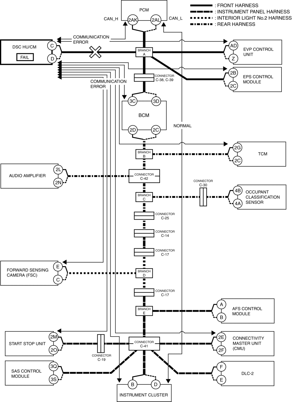
Malfunction diagnosis procedure
-
If a vehicle with a malfunction in a system controlled by a CAN system related module is brought in, verify the repair order form and the malfunctioning symptom first, then perform CAN malfunction diagnosis to determine if the malfunction cause is in the CAN system or not.
-
For CAN malfunction diagnosis, the voltage at the CAN connection terminal on the DLC-2 is measured, and based on the measured value, the CAN circuit can be examined or the malfunction symptom can be determined.
-
If the malfunction symptom is not an open circuit, inspect the voltage or continuity at the CAN circuit and determine the malfunctioning location.
-
If the malfunction symptom is an open circuit, determine the area of the open circuit by using the displayed communication error DTC and the module in which communication has failed.
Ex.) Open circuit location determination procedure
1. Verify the CAN system-related module DTCs and the failed module using the Mazda Modular Diagnostic System (M-MDS).
|
DTC output module |
Mazda Modular Diagnostic System (M-MDS) display |
Output DTC |
|
PCM |
PCM |
U0121:00 |
|
EVP control unit |
EVP |
U0121:00 |
|
U0121:02 |
||
|
U0121:87 |
||
|
EPS control module |
EPS |
U0121:00 |
|
BCM |
BCM |
U0121:00 |
|
TCM |
TCM |
U0121:00 |
|
Forward sensing camera (FSC) |
FSC |
U0121:00 |
|
Start stop unit |
SSU |
U0121:00 |
|
U0121:87 |
||
|
Connectivity master unit (CMU) |
CMU |
U0121:00 |
|
Instrument cluster |
IC |
U0121:00 |
|
Module |
Fail display |
|
DSC HU/CM |
× |
2. As a result of DTC verification, only DTCs related to DSC HU/CM and communication errors are output and the DSC HU/CM is indicated as failed, therefore there could be a malfunction in the DSC HU/CM or in the wiring harness between connector C-26, C-27 and DSC HU/CM.
Local CAN
-
Local CAN is used for communication between the following modules:
-
Between PCM and TCM (AT)
-
Between connectivity master unit (CMU), CD player, and tuner and amp unit (with center display)
-
Between audio unit, Bluetooth® unit, and CD player (without center display)
-
Between blind spot monitoring (BSM) control module (LH) and blind spot monitoring (BSM) control module (RH) (with blind spot monitoring (BSM) system)
LIN communication
-
LIN communication is used for communication between the following modules:
-
Between BCM and auto light sensor / rain sensor
-
Between BCM and electrical supply unit (ESU)
-
Between connectivity master unit (CMU) and commander switch
ISO communication
-
ISO communication is used for communication between the following modules:
-
Between rear BCM and start stop unit
Construction
CAN
-
The HS-CAN has terminator resistors built into the following units which form the CAN lines.
-
Between PCM terminals 2AK (CAN_H) and 2AL (CAN_L), resistance value: 124 ohms
-
Between instrument cluster terminals B (CAN_H) and D (CAN_L), resistance value: 120 ohms
-
The MS-CAN has terminal resistors built into the following units which form the CAN lines.
-
Between instrument cluster terminals C (CAN_H) and E (CAN_L), resistance value: 120 ohms
-
Between climate control unit terminals D (CAN_H) and B (CAN_L), resistance value: 120 ohms
Local CAN
-
The local CAN has terminator resistors built into the following units which form the CAN lines.
-
Between connectivity master unit (CMU) terminals 2I (CAN_H) and 2J (CAN_L), resistance value: 120 ohms (with center display)
-
Between tuner and amp unit terminals 2O (CAN_H) and 2Q (CAN_L), resistance value: 120 ohms (with center display)
-
Between audio unit terminals 1O (CAN_H) and 1Q (CAN_L), resistance value: 120 ohms (without center display)
-
Between CD player terminals G (CAN_H) and H (CAN_L), resistance value: 120 ohms (without center display)
-
Between blind spot monitoring (BSM) control module (LH) terminals G (CAN_H) and J (CAN_L), resistance value: 120 ohms (with blind spot monitoring (BSM) system)
-
Between blind spot monitoring (BSM) control module (RH) terminals G (CAN_H) and J (CAN_L), resistance value: 120 ohms (with blind spot monitoring (BSM) system)
-
Between PCM terminals 1A (CAN_H) and 1B (CAN_L), resistance value: 120 ohms
-
Between TCM terminals 1AI (CAN_H) and 1AE (CAN_L), resistance value: 120 ohms
LIN communication
-
The LIN communication has drivers built into the following units which form the LIN communication lines.
-
BCM
-
Auto light sensor / rain sensor
-
Electrical supply unit (ESU)
-
Connectivity master unit (CMU)
-
Commander switch
ISO communication
-
The ISO communication has drivers built into the following units which form the ISO communication lines.
-
Start stop unit
-
BCM