LANE DEPARTURE WARNING SYSTEM (LDWS)
2016 – MX-5 – i-ACTIVSENSE
LANE DEPARTURE WARNING SYSTEM (LDWS)
Outline
-
The Lane Departure Warning System (LDWS) recognizes vehicle lane lines on a road using the forward sensing camera (FSC) installed to the windshield, and if the vehicle departs from its lane unbeknownst to the driver, the system alerts the driver of the lane departure using a warning indication and warning sound.
WARNING:
-
The lane departure warning system (LDWS) is only a supplementary system for the prevention of a lane departure, however the lane departure warning system (LDWS) functions have limitations. Relying solely on the lane departure warning system (LDWS) and neglecting prudent steering wheel operation could cause an unexpected accident resulting in death or serious injury. Do not rely solely on the lane departure warning system (LDWS). Always make lane corrections using the steering wheel and drive safely.
-
The lane departure warning system (LDWS) may not operate normally under the following conditions:
-
Poor vehicle lane line visibility due to adverse weather (rain, snow, fog)
-
Poor vehicle lane line visibility due to backlight, snow on the road, water puddles, road ruts
-
Poor vehicle lane line visibility due to cracks and fissures in the vehicle lane
-
Vehicle lane lines intersect with complexity due to additions or reductions of travel lanes
-
Vehicle lane marking is not completely erased after road maintenance, two or more lane lines next to each other
-
Vehicle lane lines not recognized due to vehicle ahead
CAUTION:
-
If the forward sensing camera (FSC) aiming is not completed correctly, the forward sensing camera (FSC) cannot record the camera shooting angle and the lane departure warning system (LDWS) may not operate normally. When performing the following servicing, always perform the forward sensing camera (FSC) aiming. In addition, for the forward sensing camera (FSC) aiming procedure, refer to the [FORWARD SENSING CAMERA (FSC) AIMING] in the Workshop Manual.
-
Forward sensing camera (FSC) replacement
-
Forward sensing camera (FSC) clip replacement
-
Windshield replacement
Functions
-
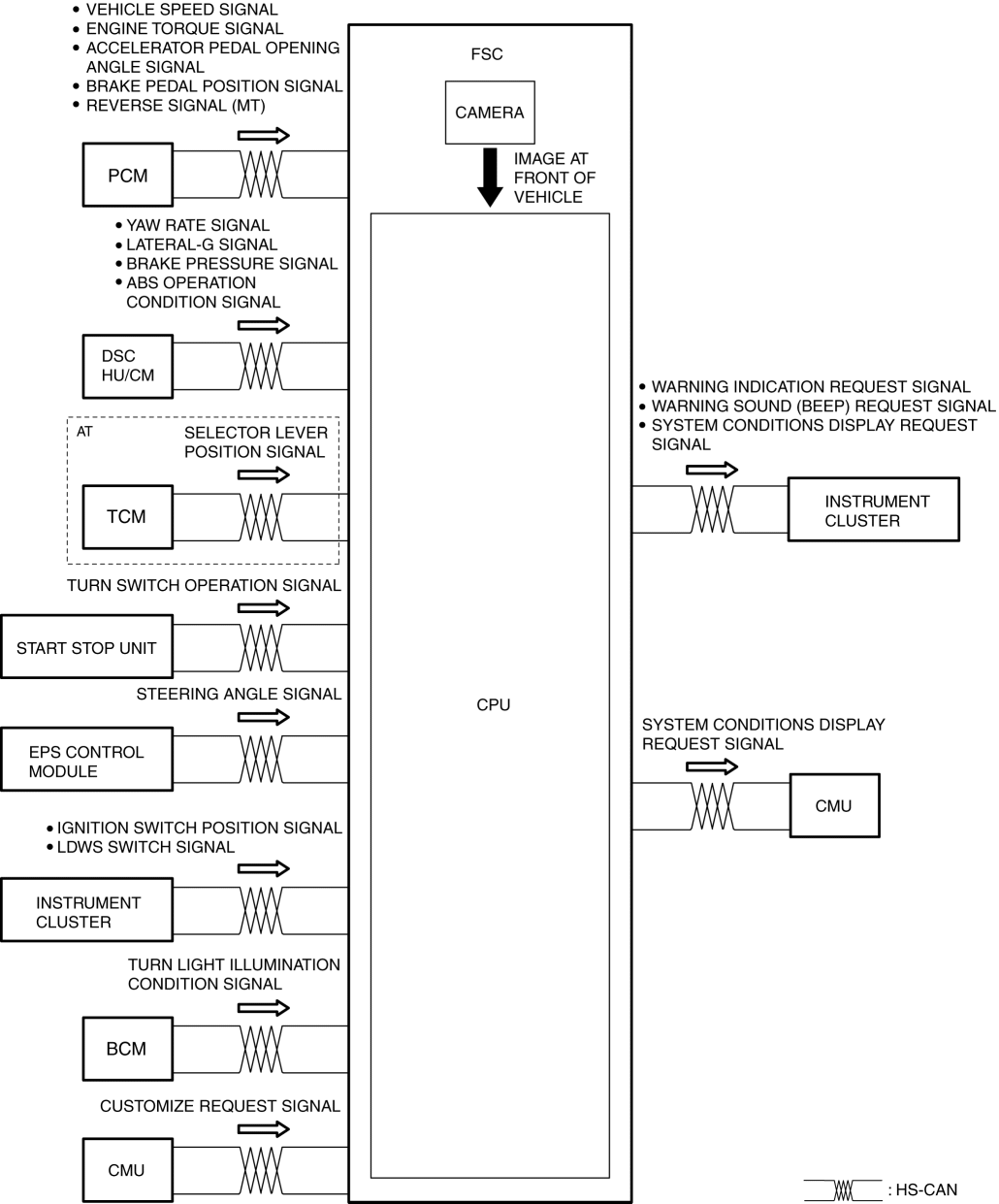
The forward sensing camera (FSC) sets warning-trigger lines based on the vehicle lane lines recognized by the camera, and if the vehicle contacts one of these warning-trigger lines it activates the warning indicator and warning sound. For details on the forward sensing camera (FSC) and warning-trigger lines, refer to [FORWARD SENSING CAMERA (FSC)]. (See FORWARD SENSING CAMERA (FSC).)
Driver operation determination function
-
The forward sensing camera (FSC) determines the following driving operations as the driver’s intentions and controls the warning operation.
-
After the turn switch is operated, the vehicle lane is changed within 60 s.
-
The steering wheel is turned at a certain angle or more, and the vehicle lane is changed.
-
The accelerator pedal is depressed a certain amount or more, and the vehicle lane is changed.
-
The brake pedal is depressed a certain amount or more and the vehicle departs from its lane.
System conditions display function (with center display)
-
The forward sensing camera (FSC) displays the system status using the warning indication in the center display.
|
LDWS switch |
Condition |
Center display |
|
OFF |
System is off |
No display |
|
ON |
Vehicle lane lines are recognized at a vehicle speed of 65 km/h {40 mph} or more |
|
|
While warning is triggered |
||
|
Vehicle speed is 60 km/h {37 mph} or less |
||
|
Vehicle lane lines are not recognized |
||
|
Forward sensing camera (FSC) detects camera/windshield fogging |
Warning display*1 |
|
|
Forward sensing camera (FSC) detects that the camera/windshield is dirty |
||
|
Lane departure warning system (LDWS) has a malfunction |
||
|
Forward sensing camera (FSC) has a malfunction |
- *1
- For the warning display content on the center display, refer to the [CENTER DISPLAY]. (See CENTER DISPLAY [WITH CENTER DISPLAY].)
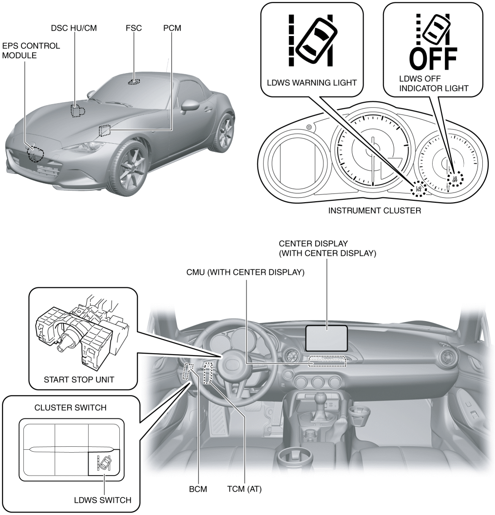
Structural View
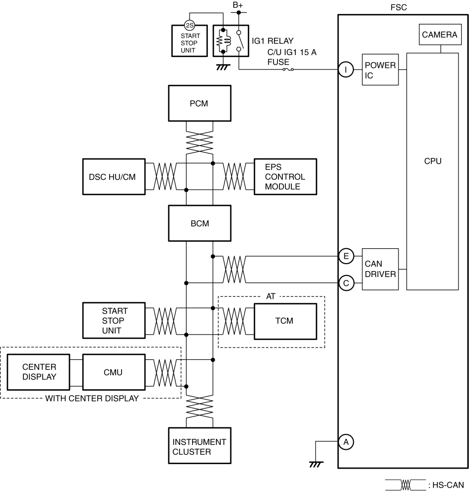
System Wiring Diagram
Block Diagram
Operation
Operation condition
-
The warning is triggered when all of the following conditions are met:
-
LDWS switch is on (system on)
-
Vehicle speed signal of approx. 65 km/h {40 mph} or more is received from PCM
-
Vehicle contacts warning-trigger line unbeknownst to driver
Operation
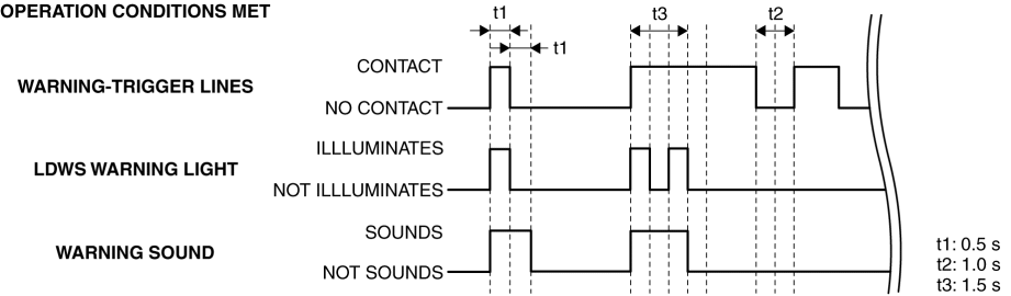
-
The period of time in which the warning is triggered differs by the period of time in which the vehicle is contacting the warning-trigger line.
-
Vehicle contacts warning-trigger line for less than approx. 1 s: Warning triggers for 1 s
-
Vehicle contacts warning-trigger line for approx. 1 s or more: Warning triggers for 1.5 s
-
If the warning is triggered one time, the warning will not trigger again until the vehicle travels within the warning-trigger lines for a period of approx. 2 s.
-
One of the following two available types of warning sounds can be selected using the personalization feature. (Initial setting is beep sound)
-
Beep sound output by instrument cluster
-
Rumble strip sound*1 output by tuner and AMP unit (TAU)
- *1
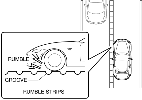
- A rumble strip is a series of grooves in the road pavement surface positioned at specific intervals, and when the vehicle passes over it a rumble sound is produced and an uncomfortable vibration can be felt which alerts the driver that the vehicle is departing from the lane lines. The rumble strip sound is a reproduction of the sound which occurs when a vehicle passes over a rumble strip.
-
Rumble strip sound (with center display)
-
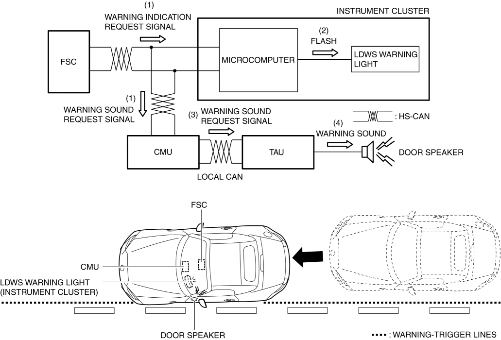
If the forward sensing camera (FSC) determines that the vehicle has contacted a warning-trigger line, it sends (1) a warning sound request signal to the connectivity master unit (CMU), and a warning indication request signal to the instrument cluster.
-
When the instrument cluster receives the warning indication request signal from the forward sensing camera (FSC), it flashes (2) the LDWS warning light in the instrument cluster.
-
When the connectivity master unit (CMU) receives the warning sound request signal from the forward sensing camera (FSC), it sends (3) the warning sound request signal to the tuner and AMP unit (TAU).
-
When the tuner and AMP unit (TAU) receives the warning sound request signal from the connectivity master unit (CMU), it stops output from either the left or right door speaker and outputs (4) a rumble strip sound.
-
Beep sound
-
For the beep sound operation, refer to the [LANE DEPARTURE WARNING SOUND]. (See LANE DEPARTURE WARNING SOUND.)