DRIVE-BY-WIRE CONTROL [SKYACTIV-G 2.0]
2016 – MX-5 – Engine
DRIVE-BY-WIRE CONTROL [SKYACTIV-G 2.0]
Outline
-
To realize the driving required by the driver, the throttle valve actuator is controlled by electric signals and an optimum target throttle valve opening angle is calculated, and not by physically linking the accelerator pedal operation and throttle valve operation using a throttle cable.
-
The drive-by-wire control performs the following controls.
Control Table
|
Control name |
Control outline |
|
Idle air control |
|
|
Accelerator control |
|
|
Traction control |
|
|
Excess engine speed control |
|
|
Overspeed control |
|
|
Electric variable valve timing cooperation control |
|
|
Engine oil temperature control |
|
|
Cruise control system (with cruise control system) |
|
|
Brake override system |
|
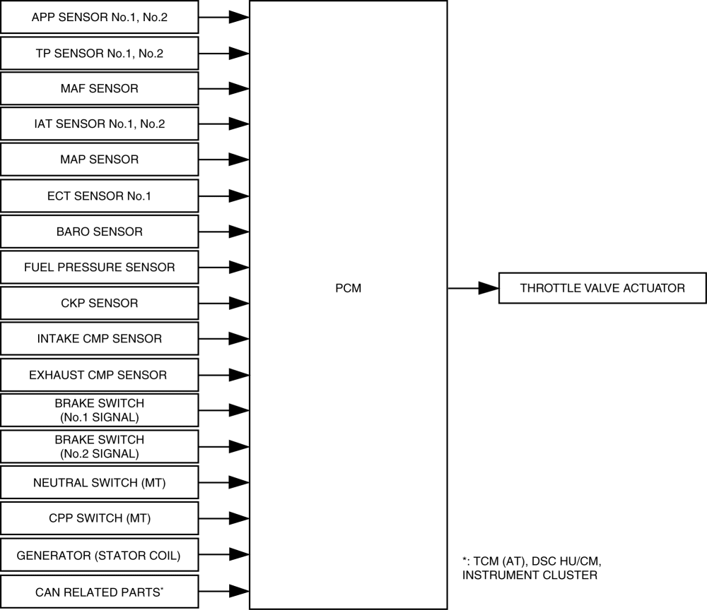
Block Diagram
Operation
Idle air control
-
The idle speed control controls the throttle valve opening angle according to the engine torque to achieve the target idle speed.
-
The PCM drives the throttle valve actuator so that the actual idle speed approaches the target idle speed.
-
Target idle speed calculation
-
Calculates the target idle speed according to the purpose of use such as the basic idle speed and fast idle up*.
-
*: The catalytic converter is activated quickly after cold-engine starts. (Engine speed increases up to approx. 2,000 rpm)
-
Engine torque calculation to achieve target idle speed
-
The engine torque is controlled in consideration of the following factors to achieve the target idle speed.
-
Feedback: The torque difference is added so that the actual idle speed approaches the target idle speed.
-
Engine mechanical resistance: Changes according to the engine coolant temperature.
-
Pumping loss: Changes based on the valve timing and intake air pressure.
-
External electric load: Changes depending on the A/C ON/OFF, generator power generation amount.
-
D position torque: Adds load torque from torque converter. (AT)
Accelerator control
-
The accelerator control controls the throttle valve opening angle according to the accelerator pedal depression amount.
-
The PCM controls the throttle valve actuator so that the actual throttle valve opening angle approaches the final target throttle valve opening angle.
-
The target throttle valve opening angle is determined by the transmission gear position, accelerator pedal depression amount, and vehicle speed.
-
Because deviation in the throttle valve opening angle due to deterioration over time is corrected when the ignition is switched off, the PCM operates the fully-closed learning function. The fully-closed learning function is a function for learning the fully-closed throttle valve position.
Traction control
-
The traction control calculates the target throttle valve opening angle based on the torque up/down request signal and engine speed from the DSC HU/CM.
Excess engine speed control
-
If the engine reaches a high engine speed*, the excess engine speed control stabilizes the engine speed lower than the excess speed range to protect the engine.
- *
- Value fluctuates depending on various conditions.
Overspeed control
-
If the vehicle reaches a high vehicle speed, the excess vehicle speed control closes the throttle valve to keep the vehicle speed below the speed limit.
Electric variable valve timing cooperation control
-
The electric variable valve timing coordinated control calculates the target throttle valve opening angle according to the changes in the phase of the intake valve timing due to the electrical variable valve timing control.
Engine oil temperature control
-
If 6 min have elapsed with the following condition met, the engine oil temperature control lowers the engine speed by decreasing the throttle valve opening angle to protect the engine (determines engine oil temperature is excessively high). DTC P117A:00 is recorded simultaneously.
-
Transmission in 5th
-
Engine speed: 6,100 rpm or more
-
ECT: 88.5 °C {191 °F} or more
Cruise control system (with cruise control system)
-
Calculates the throttle valve opening angle based on the deviation of the actual vehicle speed from the set vehicle speed which was set with the cruise control switch and the throttle valve actuator.
-
The PCM controls the actual vehicle speed so that it is close to the set vehicle speed.
-
The cruise control includes the cruise control operation condition and the cruise control stop condition.
-
Cruise control operation condition
-
When all of the following conditions are met, execution of the cruise control system is enabled (cruise control standby status).
-
ON switch: On
-
Vehicle speed: Exceeds 25 km/h {16 mph}
-
Cruise control stop condition
-
When any of the following conditions are met even while in cruise control, the PCM stops the cruise control and clears the set vehicle speed.
-
Ignition: Off
-
OFF/CANCEL switch: On (long-press)
-
Cruise control related DTCs (P0504:00) detected
-
When any of the following conditions are met even while in cruise control, the PCM stops the cruise control while storing the set vehicle speed.
-
OFF/CANCEL switch: On
-
Transmission range (TR) switch: P/N position (AT)
-
CPP switch: ON (clutch pedal depressed) (MT)
-
Neutral switch: ON (neutral position) (MT)
-
Vehicle speed: Less than 20.5 km/h {12.7 mph}
-
Brake switch: On (brake pedal depressed)
-
Brake fluid pressure: 0.3 MPa {3 kgf/cm2, 44 psi} or more
-
Actual vehicle speed is 15 km/h {9.3 mph} or more lower than the set vehicle speed during cruise control (during ascent)
-
Parking brake lever pulled
-
Cruise control function
-
The cruise control includes accelerating, coasting, resume, tap-down, tap-up and downshift functions.
Function List
|
Function |
Contents |
|
Accelerating |
|
|
Coasting |
|
|
Resume |
|
|
Tap down |
|
|
Tap-up |
|
|
Downshift |
|
Brake override system
-
Brake override system operation conditions
-
It gives priority to the brake operation if a malfunction occurs with the accelerator pedal such as if the accelerator pedal is depressed and does not return. The throttle valve is closed if the brake pedal is depressed while the accelerator pedal is in a depressed condition until the vehicle is safely decelerated and comes to a complete stop.
|
Operation start conditions |
|
|
Operation complete conditions |
NOTE:
|
- *1
- Specified time is 0.6???10 s according to braking force calculated in PCM.
- *2
- Specification is 1,200 rpm while vehicle is stopped and 1,100 rpm while vehicle is driven.
-
Prevention of brake override system unnecessary operation
-
If a servicing procedure requiring the brake pedal and the accelerator pedal to be depressed simultaneously is performed, unnecessary operation of the brake override system can be prevented, if necessary.
NOTE:
-
The operation of the emergency signal system (ESS) can be also canceled by performing the procedure for preventing unnecessary operation of the brake override system.
|
Cancel conditions |
|
|
Recovery condition |
|
-
Master warning light illumination request
-
If any of the following conditions is met, the PCM sends the master warning light illumination request signal to the instrument cluster. The master warning light illuminates to alert the driver that there is a malfunction in the brake system.
-
Brake switch (No.1 signal) has a malfunction
-
Brake switch (No.2 signal) has a malfunction
-
Master warning light flash request
-
If the cancel condition for preventing unnecessary operation of the brake override system is implemented, the PCM sends a brake override system cancel execution signal to the instrument cluster. The master warning light flashes to alert the driver that the brake override system is released.