ENGINE CONTROL SYSTEM [SKYACTIV-G 2.0]
2016 – MX-5 – Engine
ENGINE CONTROL SYSTEM [SKYACTIV-G 2.0]
Outline
-
L-jetronic*1 and D-jetronic*2 types have been adopted for the intake air amount measurement to realize stable combustion free from abnormal combustion.
-
MAF sensor adopted
-
MAP sensor adopted
-
IAT sensor No.1 and No.2 adopted
-
To improve the fuel economy and emission performance, an electric variable valve timing control has been adopted for the intake side, and a hydraulic variable valve timing control for the exhaust side. The electric type is adopted for the intake side to achieve expanded valve overlap and delayed closing of the intake valve (enlarged intake valve opening angle).
-
Intake CMP sensor adopted
-
Electric variable valve timing motor/driver adopted
-
Electric variable valve timing relay adopted
-
Exhaust CMP sensor adopted
-
Intake side: Electric variable valve timing control
-
Exhaust side: Hydraulic variable valve timing control
-
Engine hydraulic pressure switching control has been adopted to reduce the oil pump operation load on the engine.
-
Engine oil solenoid valve adopted
-
To improve engine reliability, an ion sensor has been adopted which detects pre-ignition.
- *1
- The intake air amount is directly detected by measuring the amount of intake air flow using the MAF sensor.
- *2
- The intake air amount is detected indirectly by measuring the intake manifold pressure (pressure between downstream of the throttle valve and intake manifold) using the MAP sensor.
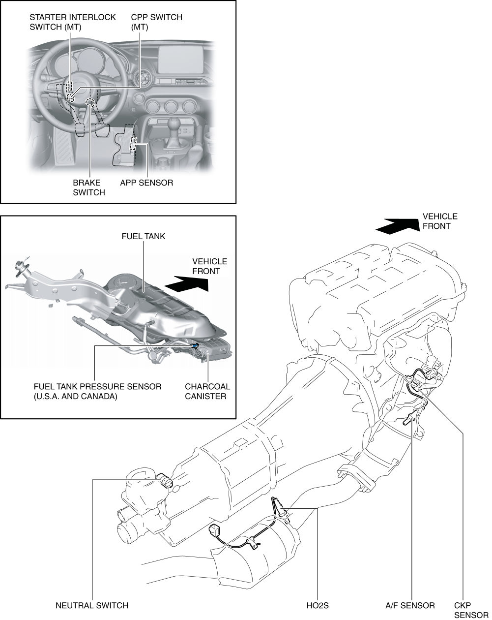
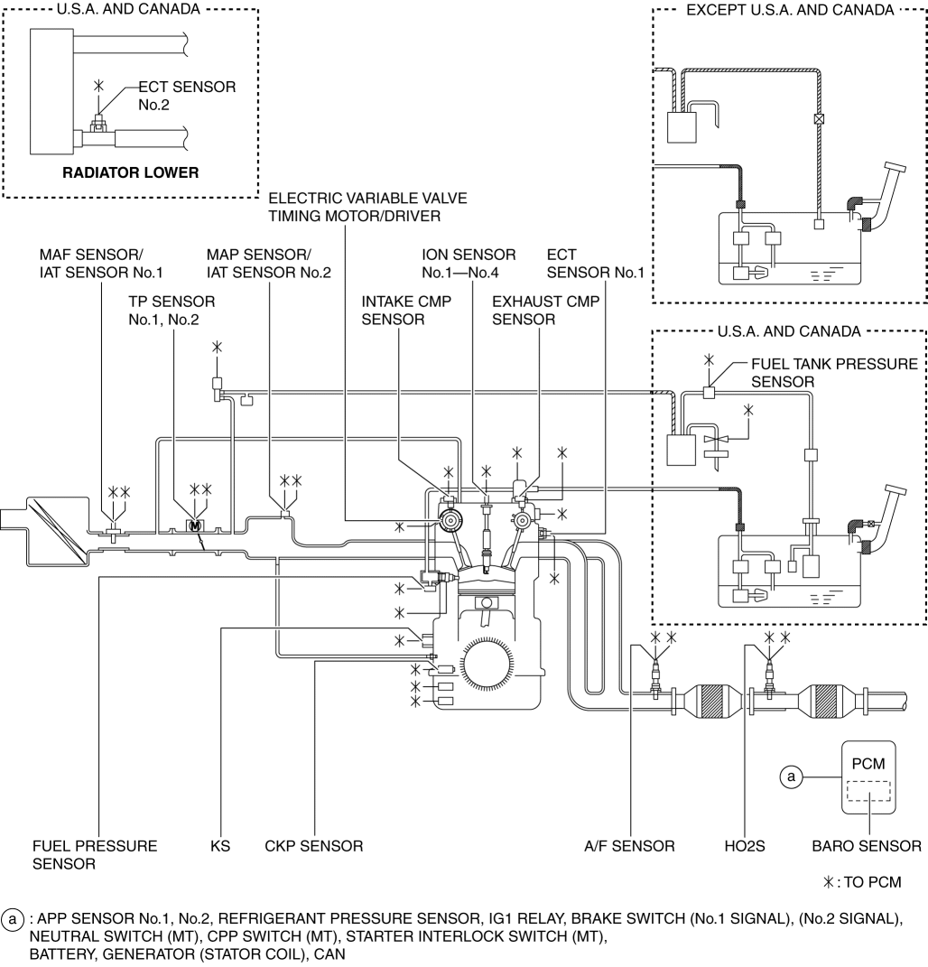
Structural View
Input device
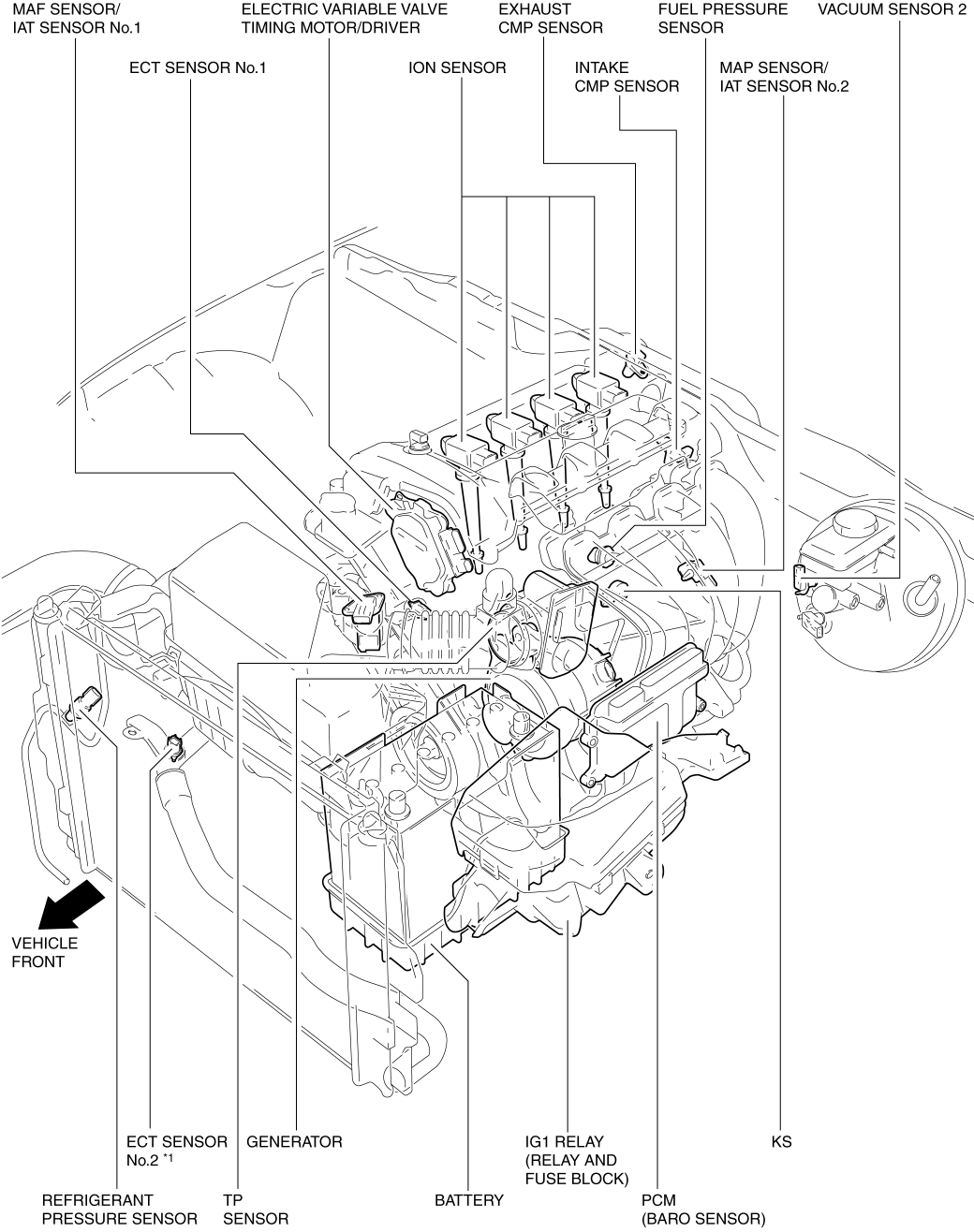
- *1
- U.S.A. and CANADA
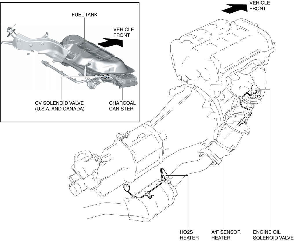
Output device
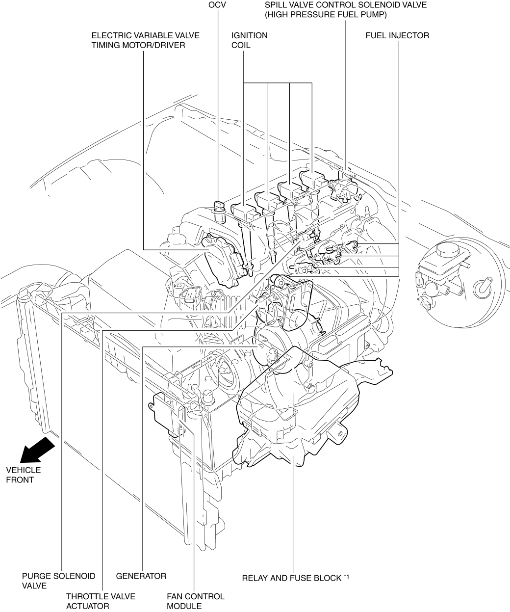
- *1
- Main relay, fuel injector relay, fuel pump relay, A/C relay, cooling fan relay, starter relay, electric variable valve timing relay
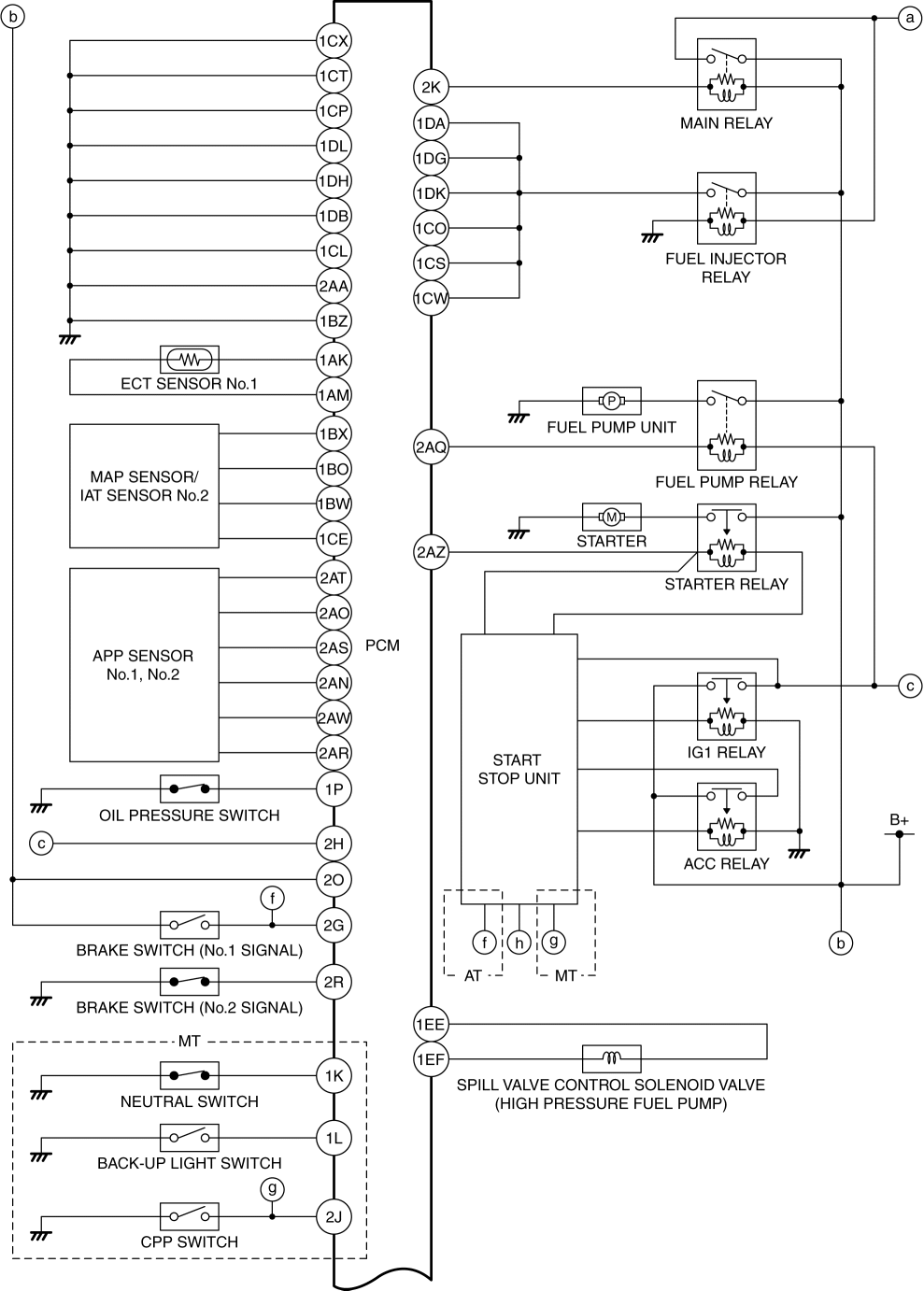
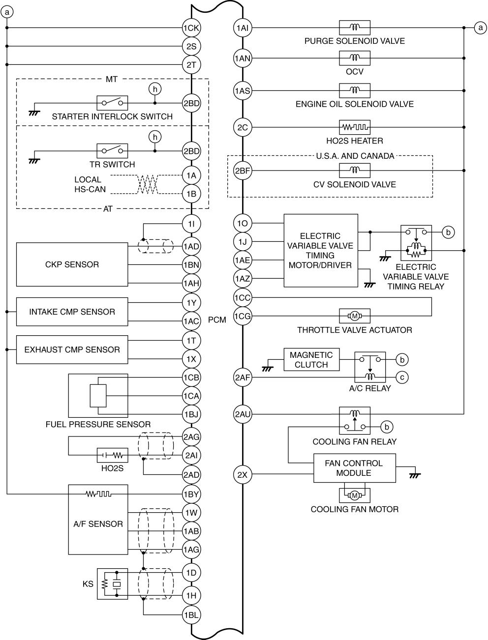
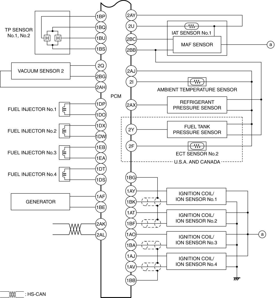
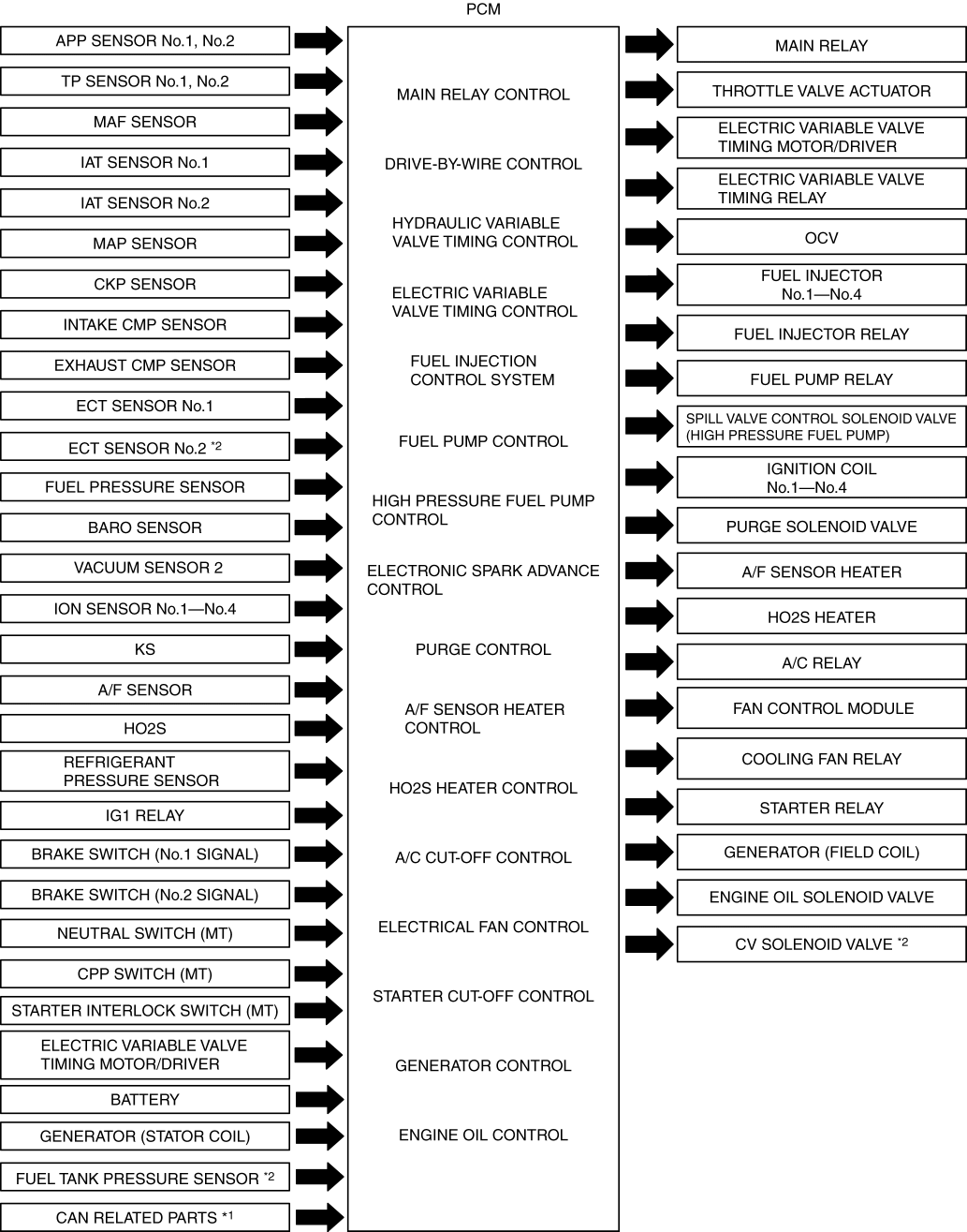
System Diagram
Input device
Output device

System Wiring Diagram
Block Diagram
- *1
- DSC HU/CM, TCM (AT), instrument cluster, BCM, start stop unit
- *2
- U.S.A. and CANADA
Relation Chart
-
Each control system and their related input and output parts are as follows.
Input device
×: Applicable
|
Item |
|
|
|
|
|
|
|
|
|
|
|
|
|
|
|
|
|
APP sensor No.1, No.2 |
× |
× |
× |
× |
× |
× |
× |
|||||||||
|
TP sensor No.1, No.2 |
× |
× |
× |
|||||||||||||
|
MAF sensor |
× |
× |
× |
× |
× |
× |
× |
× |
× |
× |
× |
|||||
|
IAT sensor No.1 |
× |
× |
× |
× |
× |
× |
||||||||||
|
IAT sensor No.2 |
× |
× |
× |
× |
||||||||||||
|
MAP sensor |
× |
× |
× |
× |
× |
× |
||||||||||
|
CKP sensor |
× |
× |
× |
× |
× |
× |
× |
× |
× |
× |
× |
× |
× |
× |
× |
|
|
Intake CMP sensor |
× |
× |
× |
× |
||||||||||||
|
Exhaust CMP sensor |
× |
× |
× |
× |
× |
|||||||||||
|
ECT sensor No.1 |
× |
× |
× |
× |
× |
× |
× |
× |
× |
× |
× |
× |
× |
|||
|
Fuel pressure sensor |
× |
× |
× |
× |
||||||||||||
|
BARO sensor |
× |
× |
× |
× |
× |
|||||||||||
|
Ion sensor No.1???No.4 |
× |
× |
||||||||||||||
|
KS |
× |
|||||||||||||||
|
A/F sensor |
× |
× |
||||||||||||||
|
HO2S |
× |
|||||||||||||||
|
Refrigerant pressure sensor |
× |
× |
||||||||||||||
|
IG1 relay |
× |
× |
× |
× |
× |
× |
× |
× |
× |
|||||||
|
Brake switch (No.1 signal) |
× |
|||||||||||||||
|
Brake switch (No.2 signal) |
× |
|||||||||||||||
|
CPP switch (MT) |
× |
× |
× |
× |
||||||||||||
|
Starter interlock switch (MT) |
× |
|||||||||||||||
|
Neutral switch (MT) |
× |
× |
× |
× |
||||||||||||
|
Electric variable valve timing motor/driver |
× |
|||||||||||||||
|
Battery |
× |
× |
× |
× |
× |
× |
||||||||||
|
Generator (Stator coil) |
× |
|||||||||||||||
|
CAN related parts*1 |
× |
× |
× |
× |
× |
× |
× |
|||||||||
|
ECT sensor No.2*2 |
Only used for OBD. |
|||||||||||||||
|
Fuel tank pressure sensor*2 |
Only used for OBD. |
|||||||||||||||


- *1
- DSC HU/CM, TCM (AT), instrument cluster, BCM, start stop unit
- *2
- U.S.A. and CANADA
Output device
×: Applicable
|
Item |
|
|
|
|
|
|
|
|
|
|
|
|
|
|
|
|
|
Main relay |
× |
|||||||||||||||
|
Throttle valve actuator |
× |
|||||||||||||||
|
Electric variable valve timing motor/driver |
× |
× |
||||||||||||||
|
Electric variable valve timing relay |
× |
|||||||||||||||
|
OCV |
× |
|||||||||||||||
|
Fuel injector No.1???No.4 |
× |
|||||||||||||||
|
Fuel injector relay |
× |
|||||||||||||||
|
Fuel pump relay |
× |
|||||||||||||||
|
Spill valve control solenoid valve (High pressure fuel pump) |
× |
|||||||||||||||
|
Ignition coil No.1???No.4 |
× |
|||||||||||||||
|
Purge solenoid valve |
× |
|||||||||||||||
|
A/F sensor heater |
× |
|||||||||||||||
|
HO2S heater |
× |
|||||||||||||||
|
A/C relay |
× |
|||||||||||||||
|
Cooling fan relay |
× |
|||||||||||||||
|
Fan control module |
× |
|||||||||||||||
|
Starter relay |
× |
|||||||||||||||
|
Generator (Field coil) |
× |
|||||||||||||||
|
Engine oil solenoid valve |
× |
|||||||||||||||
|
CV solenoid valve*1 |
Only used for OBD. |
|||||||||||||||
- *1
- U.S.A. and CANADA