DIAGNOSTIC ASSIST FUNCTION [CONNECTIVITY MASTER UNIT]
2016 – MX-5 – Body and Accessories
DIAGNOSTIC ASSIST FUNCTION [CONNECTIVITY MASTER UNIT]
Activation Procedure
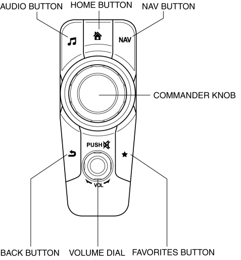
Using commander switch
1. Switch the ignition to ACC or ON (engine off or on).
2. Press the following buttons simultaneously for 2 s or more.
-
Volume dial
-
AUDIO button
-
FAVORITES button
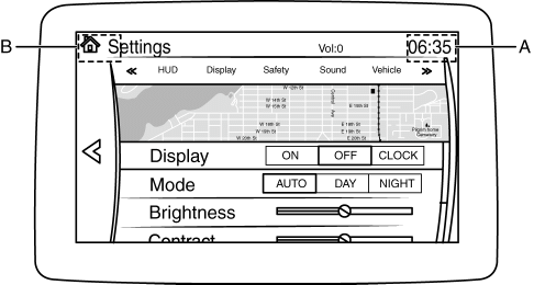
Using center display
1. Switch the ignition to ACC or ON (engine off or on).
2. Display the display setting screen in the center display.
-
Select [Settings] on the center display.
-
Select [Screen] on the center display.
3. Operate the center display in the following order.
-
Touch and hold the right upper area of the screen (area A in figure) until a beep is heard (approx. 5 s or more).
-
Touch and hold the left upper area of the screen (area B in figure) until a beep is heard (approx. 5 s or more).
Diagnostic Assist Code Input Procedure
Diagnostic assist code input screen
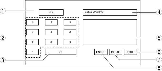
|
No. |
Name |
Content/function |
|
1 |
Diagnostic assist code display screen |
Displays the diagnostic assist code. |
|
2 |
Diagnostic assist code input switch |
Inputs the diagnostic assist code. |
|
3 |
DEL switch |
Clears the diagnostic assist code. |
|
4 |
Diagnostic content display screen |
Displays the diagnostic content. |
|
5 |
Diagnostic results display screen |
Displays the diagnostic results. |
|
6 |
EXIT switch*1/END switch*2 |
Cancels the diagnostic assist function./Stops the diagnostic assist function being performed. |
|
7 |
CLEAR switch |
Clears the diagnostic result display. |
|
8 |
ENTER switch |
Transfers to the diagnostic assist function. |
- *1
- Displayed while the diagnostic assist function is not performed.
- *2
- Displayed while the diagnostic assist function is being performed.
Using commander switch
1. Input the diagnostic assist code by rotating the commander knob.
2. Press the commander knob.
3. Perform the inspection according to the diagnostic assist code list. (See Diagnostic Assist Code List.)
NOTE:
-
If [- REJECTED] is displayed, the inspection cannot be performed because communication is not enabled between the related parts, or the conditions are not met even if communication is enabled. Therefore, verify the display [- REJECTED] referring to the following procedure. (See [- REJECTED] is displayed.)
Using center display
1. Input the diagnostic assist code by pressing the ???Diagnostic assist code input switch???.
2. Press ???ENTER???.
3. Perform the inspection according to the diagnostic assist code list. (See Diagnostic Assist Code List.)
NOTE:
-
If [- REJECTED] is displayed, the inspection cannot be performed because communication is not enabled between the related parts, or the conditions are not met even if communication is enabled. Therefore, verify the display [- REJECTED] referring to the following procedure. (See [- REJECTED] is displayed.)
[- REJECTED] is displayed
1. Switch the ignition off.
2. Launch the diagnostic assist function. (See Activation Procedure.)
3. Input the diagnostic assist code. (See Diagnostic Assist Code Input Procedure.)
4. Verify that [- REJECTED] is not displayed.
-
If [- REJECTED] is displayed, perform the DTC inspection or inspect the part related to the diagnostic content. (See DTC INSPECTION [CONNECTIVITY MASTER UNIT].)
Ending Procedure
1. While the inspection is being performed, press ???END??? to return to the diagnostic assist code input screen.
NOTE:
-
The diagnostic assist function cannot be canceled while the diagnostic assist function is being inspected.
2. Cancel the diagnostic assist function by pressing ???EXIT???.
NOTE:
-
If the diagnostic assist function is canceled, it returns to a different screen depending on the way in which the diagnostic assist function was launched.
-
If launched using the commander switch: The screen directly before launching the diagnostic assist function
-
If launched not using the commander switch: The display setting screen
Diagnostic Assist Code List
|
No. |
Center display (diagnostic content) |
Content/function |
Reference |
|
01 |
CD Test |
CD player inspection |
|
|
02 |
Clear DTC |
DTC clearing |
|
|
03 |
Read AVC DTC |
Inspection of all DTCs related to module |
(See Diagnostic Assist Code ???03/04/05/06??? DTC Inspection.) |
|
04 |
Read CMU DTC |
DTC inspection for connectivity master unit (CMU) |
(See Diagnostic Assist Code ???03/04/05/06??? DTC Inspection.) |
|
05 |
Read TAU DTC |
DTC inspection for tuner and amp unit (TAU) |
(See Diagnostic Assist Code ???03/04/05/06??? DTC Inspection.) |
|
06 |
Read CD DTC |
DTC inspection for CD player |
(See Diagnostic Assist Code ???03/04/05/06??? DTC Inspection.) |
|
07 |
Read DTV DTC |
Does not operate due to unavailability of applicable DTC. |
|
|
08 |
Software Reset AVC |
Do not operate because item is for manufacturer use. |
|
|
09 |
Software Version Display (CD) |
Software version verification |
(See Diagnostic Assist Code ???09/53/57/68/69/93??? Software Version Verification.) |
|
10 |
Part Number Readout CD/DVD |
Part number verification |
(See Diagnostic Assist Code ???10/85??? Part Number Verification.) |
|
21 |
DVD Test Mode Enable |
Do not operate because item is for manufacturer use. |
|
|
22 |
DVD Test Mode Disable |
Do not operate because item is for manufacturer use. |
|
|
24 |
Vehicle Data Transfer |
Do not operate because item is for manufacturer use. |
|
|
25 |
Antenna Continuity Status |
Antenna control output condition inspection |
(See Diagnostic Assist Code ???25??? Antenna Control Output Condition Inspection.) |
|
26 |
DTV Test Mode ON |
Do not operate because item is for manufacturer use. |
|
|
27 |
DTV Test Mode OFF |
Do not operate because item is for manufacturer use. |
|
|
28 |
HD Certification AM (Main Tuner) |
Do not operate because item is for manufacturer use. |
|
|
53 |
Software Version Display (CMU) |
Software version verification |
(See Diagnostic Assist Code ???09/53/57/68/69/93??? Software Version Verification.) |
|
57 |
Software Version Display (VIP) |
Software version verification |
(See Diagnostic Assist Code ???09/53/57/68/69/93??? Software Version Verification.) |
|
58 |
Vehicle Info |
Configuration information verification |
(See Diagnostic Assist Code ???58??? Configuration Information Verification.) |
|
59 |
CMU Serial Number Readout |
Individual number verification |
(See Diagnostic Assist Code ???59??? Individual Number Verification.) |
|
61 |
Vehicle Signal (Unit Status) |
Vehicle signal verification |
(See Diagnostic Assist Code ???61??? Vehicle Signal Verification.) |
|
65 |
Commander and Switch Check |
Switch inspection |
|
|
68 |
Software version display (TFT Display) |
Software version verification |
(See Diagnostic Assist Code ???09/53/57/68/69/93??? Software Version Verification.) |
|
69 |
Software version display (Touch Panel) |
Software version verification |
(See Diagnostic Assist Code ???09/53/57/68/69/93??? Software Version Verification.) |
|
70 |
Display Check |
Display/touch panel inspection |
(See Diagnostic Assist Code ???70??? Display/Touch Panel Inspection.) |
|
72 |
GPS Data |
GPS information verification |
(See Diagnostic Assist Code ???72??? GPS Information Verification.) |
|
84 |
Maker code Display TAU |
Manufacturer verification |
(See Diagnostic Assist Code ???84??? Manufacturer Name Verification.) |
|
85 |
Part Number Readout TAU |
Part number verification |
(See Diagnostic Assist Code ???10/85??? Part Number Verification.) |
|
86 |
Radio Test Mode AM (Main) |
Do not operate because item is for manufacturer use. |
|
|
87 |
HD Certification FM (Main Tuner) |
Do not operate because item is for manufacturer use. |
|
|
88 |
HD Certification FM (Sub Tuner) |
Do not operate because item is for manufacturer use. |
|
|
89 |
XM Certification |
Do not operate because item is for manufacturer use. |
|
|
90 |
AM Reception Sensitivity Level Test |
Radio reception condition inspection |
(See Diagnostic Assist Code ???90??? Radio Reception Condition Inspection.) |
|
91 |
Radio Test Mode FM (Main) |
Do not operate because item is for manufacturer use. |
|
|
92 |
Radio Test Mode FM (Sub) |
Do not operate because item is for manufacturer use. |
|
|
93 |
Software Version Display (TAU) |
Software version verification |
(See Diagnostic Assist Code ???09/53/57/68/69/93??? Software Version Verification.) |
|
94 |
Speaker Cyclic Test (FM) |
Speaker Inspection |
|
|
95 |
Vehicle Info Display (TAU) |
Do not operate because item is for manufacturer use. |
|
|
96 |
XM Serial Number |
Do not operate because it is displayed, but, not function. |
|
|
97 |
Radio Electric Field Strength (AM) |
Do not operate because item is for manufacturer use. |
|
|
98 |
Radio Electric Field Strength (FM) |
Do not operate because item is for manufacturer use. |
|
|
99 |
Software Update |
Do not operate because item is for manufacturer use. |
|
Diagnostic Assist Code ???01??? CD Player Inspection
1. Input diagnostic assist code ???01??? according to the diagnostic assist code input procedure. (See Diagnostic Assist Code Input Procedure.)
2. After inputting the diagnostic assist code, insert the CD into the CD player within 10 s.
|
Inspection |
Display of center display (Diagnostic result) |
Content |
Action |
|
CD OK |
CD is normal
|
|
|
CD Mechanical Linkage Failure |
CD read failure
|
|
|
|
CD Signal Plausibility Failure |
CD data format error
|
|
3. Cancel the diagnostic assist function according to the ending procedure. (See Ending Procedure.)
Diagnostic Assist Code ???02??? DTC Clear
1. Input diagnostic assist code ???02??? according to the diagnostic assist code input procedure. (See Diagnostic Assist Code Input Procedure.)
2. Verify that all DTCs are cleared.
3. Cancel the diagnostic assist function according to the ending procedure. (See Ending Procedure.)
Diagnostic Assist Code ???03/04/05/06??? DTC Inspection
1. Verify the module to be inspected for DTCs referring to the chart, then input the diagnostic assist code according to the diagnostic assist code input procedure. (See Diagnostic Assist Code Input Procedure.)
NOTE:
-
The combination of DTC and diagnostic assist code can be verified in the DTC table. (See DTC TABLE [CONNECTIVITY MASTER UNIT])
-
Detection of DTCs is limited if the ignition is in the ACC position.
×: Applicable???: Not applicable
|
Diagnostic assist code |
Modules which can be verified for DTC |
||
|
Connectivity master unit (CMU) |
Tuner and amp unit (TAU) |
CD player |
|
|
03*1 |
× |
× |
× |
|
04 |
× |
??? |
??? |
|
05 |
??? |
× |
??? |
|
06 |
??? |
??? |
× |
- *1
- List of DTCs which can detect diagnostic assist codes ???04???, ???05???, and ???06??? is displayed.
2. If a DTC is displayed, repair the malfunctioning location according to the applicable DTC troubleshooting. (See DTC TABLE [CONNECTIVITY MASTER UNIT].)
3. Cancel the diagnostic assist function according to the ending procedure. (See Ending Procedure.)
Diagnostic Assist Code ???09/53/57/68/69/93??? Software Version Verification
1. Verify the module to be inspected for the software version referring to the chart, then input the diagnostic assist code according to the diagnostic assist code input procedure. (See Diagnostic Assist Code Input Procedure.)
|
Diagnostic assist code |
Software version to be verified |
|
09 |
CD player |
|
53 |
Connectivity master unit (CMU) (overall entertainment system) |
|
57 |
Connectivity master unit (CMU) (overall communication system between vehicle) |
|
68 |
Center display (TFT LCD screen control system) |
|
69 |
Center display (Touch panel control system) |
|
93 |
Tuner and amp unit (TAU) |
2. Cancel the diagnostic assist function according to the ending procedure. (See Ending Procedure.)
Diagnostic Assist Code ???10/85??? Part Number Verification
1. Verify the module to be inspected for the part number referring to the chart, then input the diagnostic assist code according to the diagnostic assist code input procedure. (See Diagnostic Assist Code Input Procedure.)
|
Diagnostic assist code |
Module to be verified for part number |
|
10 |
CD player |
|
85 |
Tuner and amp unit (TAU) |
2. Verify the part number.
NOTE:
-
Only upper 4 digits of the part number are displayed.
3. Cancel the diagnostic assist function according to the ending procedure. (See Ending Procedure.)
Diagnostic Assist Code ???25??? Antenna Control Output Condition Inspection
1. Input diagnostic assist code ???25??? according to the diagnostic assist code input procedure. (See Diagnostic Assist Code Input Procedure.)
2. Inspect the malfunctioning location according to the following table:
CAUTION:
-
Even if the system is normal, radio reception may be difficult depending on where the system is inspected (indoors/outdoors, or conditions at the location). Before inspecting the system, verify that radio reception is adequate.
-
When performing the inspection, select a frequency (radio station) with optimum reception in the area.
|
Inspection |
Display of center display (Diagnostic result) |
Action |
|
|
ANT-ON |
Good sound quality |
System is normal. |
|
Bad sound quality |
Inspect the rod antenna and antenna feeder. (See ROD ANTENNA INSPECTION.) (See ANTENNA FEEDER NO.2 INSPECTION.)
|
||
|
ANT-OFF |
Output cannot be verified |
Replace the tuner and amp unit (TAU). |
|
3. Cancel the diagnostic assist function according to the ending procedure. (See Ending Procedure.)
Diagnostic Assist Code ???58??? Configuration Information Verification
1. Input diagnostic assist code ???58??? according to the diagnostic assist code input procedure. (See Diagnostic Assist Code Input Procedure.)
2. Verify the configuration information.
|
Display of center display |
Content |
|
Destination |
Destination information |
|
CMU Types |
Recognition condition whether connectivity master unit (CMU) is equipped or not |
3. Cancel the diagnostic assist function according to the ending procedure. (See Ending Procedure.)
Diagnostic Assist Code ???59??? Individual Number Verification
1. Input diagnostic assist code ???59??? according to the diagnostic assist code input procedure. (See Diagnostic Assist Code Input Procedure.)
2. Verify the individual number of the connectivity master unit (CMU).
3. Cancel the diagnostic assist function according to the ending procedure. (See Ending Procedure.)
Diagnostic Assist Code ???61??? Vehicle Signal Verification
1. Input diagnostic assist code ???61??? according to the diagnostic assist code input procedure. (See Diagnostic Assist Code Input Procedure.)
2. Verify the vehicle signal.
|
Display of center display (Diagnostic result) |
Content |
|
Backup Camera |
Rear mount camera signal input condition |
|
ST-SW1 |
Steering switch signal (volume adjustment switch, cue/automatic band selector switch) input condition |
|
ST-SW2 |
Steering switch signal (talk button, pick-up button, hang-up button) input condition |
|
Commander |
Commander switch signal input condition |
|
GPS |
GPS antenna signal input condition |
|
Microphone |
Microphone signal input condition |
|
HUB1 |
Auxiliary jack/USB port/SD card slot hub1 signal input condition |
|
NAVI (SD) |
SD card insertion condition |
|
CD/DVD |
DVD/CD equipment recognition condition |
|
DTV |
TV tuner unit equipment recognition condition |
3. Cancel the diagnostic assist function according to the ending procedure. (See Ending Procedure.)
Diagnostic Assist Code ???65??? Switch Inspection
1. Input diagnostic assist code ???65??? according to the diagnostic assist code input procedure. (See Diagnostic Assist Code Input Procedure.)
2. Perform the steering switch inspection or commander switch inspection.
NOTE:
-
When the switch is operated, the switch operation content detected by the connectivity master unit (CMU) is displayed in the center display.
-
If the switch operation content previously detected is being displayed in the center display, newly detected content is added over it.
Steering switch inspection
|
Inspection |
Display of center display (Diagnostic result) |
Action |
|
|
|
Yes |
The steering switch is normal. |
|
No |
Inspect the steering switch. (See STEERING SWITCH INSPECTION.)
|
||
Commander switch inspection
|
Inspection |
Display of center display (Diagnostic result) |
Action |
|
|
|
Yes |
Commander switch is normal. |
|
No |
Replace the commander switch. |
||
3. Cancel the diagnostic assist function according to the ending procedure. (See Ending Procedure.)
Diagnostic Assist Code ???70??? Display/Touch Panel Inspection
1. Input diagnostic assist code ???70??? according to the diagnostic assist code input procedure. (See Diagnostic Assist Code Input Procedure.)
NOTE:
-
The display/touch panel inspection is repeated periodically until a same location in the center display is touched for 10 s or more.
|
Inspection |
Display of center display (Diagnostic result) |
Action |
|
|
If normal, [+] cursor is displayed centering around the touched area, and at the same time, the display switches in the following order.
|
Yes |
Center display is normal. |
|
No |
Replace the center display. |
||
2. Continuously touch the same location for 10 s or more.
NOTE:
-
If the display/touch panel inspection is finished, the diagnostic assist function is canceled without returning to the diagnostic assist code input screen.
-
If the diagnostic assist function is canceled, it returns to a different screen depending on the way in which the diagnostic assist function was launched.
-
If launched using the commander switch: The screen directly before launching the diagnostic assist function
-
If launched not using the commander switch: The display setting screen
Diagnostic Assist Code ???72??? GPS Information Verification
1. Input diagnostic assist code ???72??? according to the diagnostic assist code input procedure. (See Diagnostic Assist Code Input Procedure.)
2. Verify the GPS information.
NOTE:
-
GPS reception signal is updated every 1 s.
|
Display of center display (Diagnostic result) |
Content |
|
Longitude (X) |
Degree of longitude in GPS information of the current location |
|
Latitude (Y) |
Degree of latitude in GPS information of the current location |
|
Absolute Time (Z) |
Date and time information (GMT) |
|
Number of Satellites |
Number of satellites being received |
3. Cancel the diagnostic assist function according to the ending procedure. (See Ending Procedure.)
Diagnostic Assist Code ???84??? Manufacturer Name Verification
1. Input diagnostic assist code ???84??? according to the diagnostic assist code input procedure. (See Diagnostic Assist Code Input Procedure.)
2. Verify the manufacturer name.
3. Cancel the diagnostic assist function according to the ending procedure. (See Ending Procedure.)
Diagnostic Assist Code ???90??? Radio Reception Condition Inspection
1. Tune in the radio.
2. Input diagnostic assist code ???90??? according to the diagnostic assist code input procedure. (See Diagnostic Assist Code Input Procedure.)
3. Inspect the malfunctioning location according to the following table:
CAUTION:
-
Even if the system is normal, radio reception may be difficult depending on where the system is inspected (indoors/outdoors, or conditions at the location). Before inspecting the system, verify that radio reception is adequate.
-
When performing the inspection, select a frequency (radio station) with optimum reception in the area.
|
Inspection |
Display of center display (Diagnostic result) |
Action |
|
TAU AM Reception Level Test Result:10???5 |
Radio reception condition is normal
|
|
TAU AM Reception Level Test Result:4???3 |
Radio reception condition is unstable
|
|
|
TAU AM Reception Level Test Result:2???0 |
Radio reception is poor or not receivable
|
4. Cancel the diagnostic assist function according to the ending procedure. (See Ending Procedure.)
Diagnostic Assist Code ???94??? Speaker Inspection
1. Input diagnostic assist code ???94??? according to the diagnostic assist code input procedure. (See Diagnostic Assist Code Input Procedure.)
|
Inspection |
Display of center display |
Action |
|
|
??? |
Yes |
|
|
No |
Refer to the symptom troubleshooting. (See NO SOUND OUTPUT IN ALL MODES [ENTERTAINMENT SYSTEM [WITH CENTER DISPLAY]].) |
||
2. Cancel the diagnostic assist function according to the ending procedure. (See Ending Procedure.)