Menu +
Generic selectors
Exact matches only
Search in title
Search in content
Post Type Selectors

DTC B1207:86 [ELECTRICAL SUPPLY UNIT (ESU)]

< Previous Next >

2016 – MX-5 – Body and Accessories

DTC B1207:86 [ELECTRICAL SUPPLY UNIT (ESU)]

Description

Error signal received from SAS control module

Detection condition

  • The electrical supply unit (ESU) detected the following conditions for 2 s or more with the ignition switched ON (engine off or on).

    • Error signal is received from SAS control module even though the collision detection unlock function presence signal received from the BCM determines that the function is present.

Fail-safe

Not applicable

Possible cause

  • SAS control module connector or terminal malfunction

  • Electrical supply unit (ESU) connector or terminal malfunction

  • Short to ground in wiring harness between SAS control module terminal 3X and electrical supply unit (ESU) terminal 2H

  • Short to power supply in wiring harness between SAS control module terminal 3X and electrical supply unit (ESU) terminal 2H

  • Open circuit in wiring harness between SAS control module terminal 3X and electrical supply unit (ESU) terminal 2H

  • SAS control module malfunction

  • Electrical supply unit (ESU) malfunction

Diagnostic Procedure

Step

Inspection

Action

1

INSPECT SAS CONTROL MODULE CONNECTOR CONDITION

  • Switch the ignition off.

  • Disconnect the negative battery cable.

    (See NEGATIVE BATTERY CABLE DISCONNECTION/CONNECTION.)

  • Disconnect the SAS control module connector.

  • Inspect the connector engagement and connection condition and inspect the terminals for damage, deformation, corrosion, or disconnection.

  • Is the connector normal?

Yes

Go to the next step.

No

Repair or replace the connector, then go to Step 7.

2

INSPECT ELECTRICAL SUPPLY UNIT (ESU) CONNECTOR CONDITION

  • Disconnect the electrical supply unit (ESU) connector.

  • Inspect the connector engagement and connection condition and inspect the terminals for damage, deformation, corrosion, or disconnection.

  • Is the connector normal?

Yes

Go to the next step.

No

Repair or replace the connector, then go to Step 7.

3

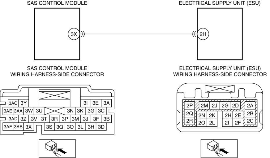
INSPECT WIRING HARNESS BETWEEN SAS CONTROL MODULE AND ELECTRICAL SUPPLY UNIT (ESU) FOR SHORT TO GROUND

  • Verify that the SAS control module and electrical supply unit (ESU) connectors are disconnected.

  • Inspect for continuity between SAS control module terminal 3X (wiring harness-side) and body ground.

  • Is there continuity?

Yes

Refer to the wiring diagram and verify whether or not there is a common connector between SAS control module terminal 3X and electrical supply unit (ESU) terminal 2H.

    If there is a common connector:

  • Determine the malfunctioning part by inspecting the common connector and the terminal for corrosion, damage, or pin disconnection, and the common wiring harness for a short to ground.

  • Repair or replace the malfunctioning part.

    If there is no common connector:

  • Repair or replace the wiring harness which has a short to ground.

Go to Step 7.

No

Go to the next step.

4

INSPECT WIRING HARNESS BETWEEN SAS CONTROL MODULE AND ELECTRICAL SUPPLY UNIT (ESU) FOR SHORT TO POWER SUPPLY

  • Verify that the SAS control module and electrical supply unit (ESU) connectors are disconnected.

  • Connect the negative battery cable.

    (See NEGATIVE BATTERY CABLE DISCONNECTION/CONNECTION.)

  • Switch the ignition ON (engine off or on).

  • Measure the voltage at the SAS control module terminal 3X (wiring harness-side).

  • Is the voltage 0 V?

Yes

Go to the next step.

No

Refer to the wiring diagram and verify whether or not there is a common connector between SAS control module terminal 3X and electrical supply unit (ESU) terminal 2H.

    If there is a common connector:

  • Determine the malfunctioning part by inspecting the common connector and the terminal for corrosion, damage, or pin disconnection, and the common wiring harness for a short to power supply.

  • Repair or replace the malfunctioning part.

    If there is no common connector:

  • Repair or replace the wiring harness which has a short to power supply.

Go to Step 7.

5

INSPECT WIRING HARNESS BETWEEN SAS CONTROL MODULE AND ELECTRICAL SUPPLY UNIT (ESU) FOR OPEN CIRCUIT

  • Switch the ignition off.

  • Disconnect the negative battery cable.

    (See NEGATIVE BATTERY CABLE DISCONNECTION/CONNECTION.)

  • Verify that the SAS control module and electrical supply unit (ESU) connectors are disconnected.

  • Inspect the wiring harness for continuity between SAS control module terminal 3X (wiring harness-side) and electrical supply unit (ESU) terminal 2H (wiring harness-side).

  • Is there continuity?

Yes

Go to the next step.

No

Refer to the wiring diagram and verify whether or not there is a common connector between SAS control module terminal 3X and electrical supply unit (ESU) terminal 2H.

    If there is a common connector:

  • Determine the malfunctioning part by inspecting the common connector and the terminal for corrosion, damage, or pin disconnection, and the common wiring harness for an open circuit.

  • Repair or replace the malfunctioning part.

    If there is no common connector:

  • Repair or replace the wiring harness which has an open circuit.

Go to Step 7.

6

VERIFY IF MALFUNCTIONING LOCATION IS SAS CONTROL MODULE DEPENDING ON REPEATABILITY

Yes

Replace the SAS control module, then go to the next step.

(See SAS CONTROL MODULE REMOVAL/INSTALLATION [STANDARD DEPLOYMENT CONTROL SYSTEM].)

(See SAS CONTROL MODULE REMOVAL/INSTALLATION [TWO-STEP DEPLOYMENT CONTROL SYSTEM].)

No

Go to Step 8.

7

VERIFY THAT REPAIRS HAVE BEEN COMPLETED

Yes

Repeat the inspection from Step 1.

Go to the next step.

No

Go to the next step.

8

VERIFY IF OTHER DTCs DISPLAYED

  • Are any other DTCs displayed?

Yes

Repair or replace the malfunctioning part according to the applicable DTC troubleshooting.

(See DTC TABLE [ELECTRICAL SUPPLY UNIT (ESU)].)

No

DTC troubleshooting completed.

< Previous Next >

© 2014 Mazda North American Operations, U.S.A.