Menu +
Generic selectors
Exact matches only
Search in title
Search in content
Post Type Selectors

DTC P0708:00 [TCM (SJ6A-EL)]

< Previous Next >

2016 – MX-5 – Transmission/Transaxle

DTC P0708:00 [TCM (SJ6A-EL)]

DTC P0708:00

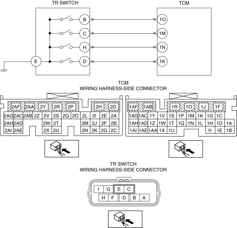
TR switch: Open circuit

DETECTION CONDITION

  • Condition: TCM normal during engine rotation

  • Status: Detects no output of TR switch at vehicle speed of 30 km/h {19 mph} or higher

  • Period: Confirmed 1 time in 30 s or more

FAIL-SAFE FUNCTION

  • When multiple position contact points are on, the selected position is determined by the following order of priority.

    • D>R>N (P)

  • When all of the position contact points are off, the D position is determined.

  • Inhibits learning control.

  • Inhibits direct mode.

  • Inhibits AAS mode.

  • Inhibits the neutral control.

  • Inhibits the reverse control.

POSSIBLE CAUSE

  • TCM connector or terminal malfunction

  • TR switch connector or terminal malfunction

  • TR switch malfunction

  • TR switch misadjustment

  • TR switch malfunction

  • Open circuit in wiring harness between TR switch terminal B and TCM terminal 1O

  • Open circuit in wiring harness between TR switch terminal C and TCM terminal 1M

  • Open circuit in wiring harness between TR switch terminal H and TCM terminal 1N

  • Open circuit in wiring harness between TR switch terminal D and TCM terminal 1K

  • Open circuit in wiring harness between TR switch terminal E and body ground

  • TCM malfunction

Diagnostic procedure

STEP

INSPECTION

ACTION

1

RECORD VEHICLE STATUS WHEN DTC WAS DETECTED TO UTILIZE WITH REPEATABILITY VERIFICATION

NOTE:

  • Recording can be facilitated using the screen capture of the PC function.

  • Record the freeze frame data/snap shot data.

Go to the next step.

2

VERIFY RELATED REPAIR INFORMATION AVAILABILITY

  • Verify related Service Bulletins and/or on-line repair information availability.

  • Is any related repair information available?

Yes

Perform repair or diagnosis according to the available repair information.

  • If the vehicle is not repaired, go to the next step.

No

Go to the next step.

3

INSPECT/ADJUST TR SWITCH

  • Is there a malfunction in the TR switch?

Yes

Adjust the TR switch, then go to Step 13.

(See TRANSMISSION RANGE (TR) SWITCH ADJUSTMENT [SJ6A-EL].)

No

Go to the next step.

4

INSPECT TR SWITCH CIRCUIT

  • Connect the TCM connector.

  • Switch the ignition ON. (engine off)

  • Inspect the voltage between TCM terminal (wiring harness-side) and body ground.

    • TCM terminal 1O

      • P position: 0 V

      • Other position: B+

    • TCM terminal 1M

      • R position: 0 V

      • Other position: B+

    • TCM terminal 1N

      • N position: 0 V

      • Other position: B+

    • TCM terminal 1K

      • D position: 0 V

      • Other position: B+

  • Are any of following terminal voltage turned on for even a moment while shifting selector lever slowly from P to D position?

Yes

Go to Step 13.

No

Go to the next step.

5

INSPECT TR SWITCH CIRCUIT

  • Are all terminal voltage 0 V in Step 3?

Yes

Go to Step 10.

No

Go to the next step.

6

INSPECT TR SWITCH CIRCUIT

  • Are there two or more terminals where the voltage is abnormal in Step 3?

Yes

Adjust the TR switch, then go to Step 13.

(See TRANSMISSION RANGE (TR) SWITCH ADJUSTMENT [SJ6A-EL].)

No

Go to the next step.

7

INSPECT TCM CONNECTOR FOR POOR CONNECTION

  • Switch the ignition off.

  • Disconnect the TCM connector.

  • Inspect for poor connection at TCM terminals 1O, 1K, 1M and 1N (such as damaged/pulled-out pins, corrosion).

  • Is there any malfunction?

Yes

Repair or replace the connector and/or terminal, then go to Step 13.

No

Go to the next step.

8

INSPECT TR SWITCH CONNECTOR FOR POOR CONNECTION

  • Disconnect the TR switch connector.

  • Inspect for poor connection at TR switch terminals B, C, D and H (part-side) (such as damaged/pulled-out pins, corrosion)

  • Are TR switch terminals normal?

Yes

Go to the next step.

No

Repair terminals or replace the TR switch, then go to Step 13.

(See TRANSMISSION RANGE (TR) SWITCH REMOVAL/INSTALLATION [SJ6A-EL].)

9

INSPECT TR SWITCH

Yes

Repair or replace the wiring harness for open circuit, then go to Step 13.

No

Replace the TR switch, then go to Step 13.

(See TRANSMISSION RANGE (TR) SWITCH REMOVAL/INSTALLATION [SJ6A-EL].)

10

INSPECT TR SWITCH GROUND CIRCUIT FOR OPEN CIRCUIT

  • Switch the ignition off.

  • Disconnect the TR switch connector.

  • Switch the ignition ON (engine off).

  • Inspect for continuity between TR switch terminal E (wiring harness-side) and body ground.

  • Is there continuity?

Yes

Go to the next step.

No

Refer to the wiring diagram and verify whether or not there is a common connector between TR switch terminal E and body ground.

    If there is a common connector:

  • Determine the malfunctioning part by inspecting the common connector and the terminal for corrosion, damage, or pin disconnection, and the common wiring harness for an open circuit.

  • Repair or replace the malfunctioning part.

    If there is no common connector:

  • Repair or replace the wiring harness which has an open circuit.

Go to Step 13.

11

INSPECT TR SWITCH CONNECTOR FOR POOR CONNECTION

  • Disconnect the TR switch connector.

  • Inspect for poor connection at TR switch terminal E (part-side) (such as damaged/pulled-out pins, corrosion)

  • Are TR switch terminals normal?

Yes

Go to the next step.

No

Repair terminals or replace the TR switch, then go to Step 13.

(See TRANSMISSION RANGE (TR) SWITCH REMOVAL/INSTALLATION [SJ6A-EL].)

12

INSPECT TR SWITCH

Yes

Go to the next step.

No

Replace the TR switch, then go to the next step.

(See TRANSMISSION RANGE (TR) SWITCH REMOVAL/INSTALLATION [SJ6A-EL].)

13

VERIFY SAME DTC IS NOT PRESENT

  • Always reconnect all disconnected connectors.

  • Clear the DTC using the M-MDS.

    (See ON-BOARD DIAGNOSTIC SYSTEM DTC INSPECTION [TCM (SJ6A-EL)].)

  • Perform the following procedure to ensure that the DTC has been resolved:

    • Start the engine.

    • Warm-up the engine to normal operating temperature.

    • Depress the brake pedal, and shift the selector lever from P to D for 2 s or more.

    • Gradually slow down and stop the vehicle.

    • Switch the ignition off.

    • Start the engine.

    • Depress the brake pedal, and shift the selector lever from P to D for 2 s or more.

  • Perform the DTC inspection using the M-MDS.

    (See ON-BOARD DIAGNOSTIC SYSTEM DTC INSPECTION [TCM (SJ6A-EL)].)

  • Is the same DTC present?

Yes

Replace the TCM, then go to the next step.

(See TCM REMOVAL/INSTALLATION [SJ6A-EL].)

No

Go to the next step.

14

VERIFY DTC TROUBLESHOOTING COMPLETED

Yes

Go to the applicable DTC inspection.

(See ON-BOARD DIAGNOSTIC SYSTEM DTC TABLE [TCM (SJ6A-EL)].)

No

DTC troubleshooting completed.

< Previous Next >

© 2014 Mazda North American Operations, U.S.A.