Menu +
Generic selectors
Exact matches only
Search in title
Search in content
Post Type Selectors

DTC P0504:00 [PCM (SKYACTIV-G 2.0)]

< Previous Next >

2016 – MX-5 – Engine

DTC P0504:00 [PCM (SKYACTIV-G 2.0)]

DTC P0504:00

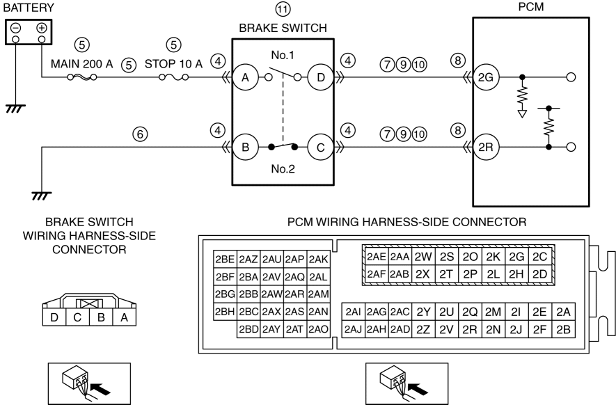
Brake switch circuit problem

DETECTION CONDITION

  • The condition in which the brake switch No.1 and No.2 signals are both on or off for 3 s or more is repeated five times when performing the brake operation.

    Diagnostic support note

  • This is a continuous monitor (other).

  • The check engine light illuminates if the PCM detects the above malfunction condition during the first drive cycle.

  • FREEZE FRAME DATA/Snapshot data is available.

  • DTC is stored in the PCM memory.

FAIL-SAFE FUNCTION

Not applicable

POSSIBLE CAUSE

CAUTION:

  • Inspect the brake switch with it installed to the brake pedal, otherwise the brake switch may not operate normally. If the brake switch is removed from the brake pedal, replace the brake switch with a new one.

  • Brake switch connector or terminals malfunction

  • Short to ground or open circuit in brake switch No.1 power supply circuit

    • Short to ground in wiring harness between MAIN 200 A fuse and brake switch terminal A

    • MAIN 200 A fuse and/or STOP 10 A fuse malfunction

    • Open circuit in wiring harness between battery positive terminal and brake switch terminal A

  • Open circuit in wiring harness between brake switch terminal B and body ground

  • Short to ground in wiring harness between the following terminals:

    • Brake switch terminal D—PCM terminal 2G

    • Brake switch terminal C—PCM terminal 2R

  • PCM connector or terminals malfunction

  • Short to power supply in wiring harness between the following terminals:

    • Brake switch terminal D—PCM terminal 2G

    • Brake switch terminal C—PCM terminal 2R

  • Open circuit in wiring harness between the following terminals:

    • Brake switch terminal D—PCM terminal 2G

    • Brake switch terminal C—PCM terminal 2R

  • Brake switch malfunction

  • PCM malfunction

Diagnostic Procedure

STEP

INSPECTION

ACTION

1

RECORD VEHICLE STATUS AT TIME OF DTC DETECTION TO UTILIZE WITH REPEATABILITY VERIFICATION

NOTE:

  • Recording can be facilitated using the screen capture function of the PC.

  • Record the FREEZE FRAME DATA/snapshot data on the repair order.

Go to the next step.

2

VERIFY RELATED REPAIR INFORMATION AVAILABILITY

  • Verify related Service Bulletins and/or on-line repair information availability.

  • Is any related repair information available?

Yes

Perform repair or diagnosis according to the available repair information.

  • If the vehicle is not repaired, go to the next step.

No

Go to the next step.

3

VERIFY RELATED PENDING CODE AND/OR DTC

Yes

Go to the applicable PENDING CODE or DTC inspection.

(See DTC P0703:00 [PCM (SKYACTIV-G 2.0)].)

No

Go to the next step.

4

INSPECT BRAKE SWITCH CONNECTOR CONDITION

  • Switch the ignition off.

  • Disconnect the brake switch connector.

  • Inspect for poor connection (such as damaged/pulled-out pins, corrosion).

  • Is there any malfunction?

Yes

Repair or replace the connector and/or terminals, then go to Step 12.

No

Go to the next step.

5

INSPECT BRAKE SWITCH NO.1 POWER SUPPLY CIRCUIT FOR SHORT TO GROUND OR OPEN CIRCUIT

  • Verify that the brake switch connector is disconnected.

  • Measure the voltage at the brake switch terminal A (wiring harness-side).

  • Is the voltage B+?

Yes

Go to the next step.

No

Inspect the MAIN 200 A fuse and STOP 10 A fuse.

  • If the fuse is blown:

    • Refer to the wiring diagram and verify whether or not there is a common connector between MAIN 200 A fuse and brake switch terminal A.

      • If there is a common connector:

      • Determine the malfunctioning part by inspecting the common connector and the terminal for corrosion, damage, or pin disconnection, and the common wiring harness for a short to ground.

      • Repair or replace the malfunctioning part.

        If there is no common connector:

      • Repair or replace the wiring harness which has a short to ground.

      • Replace the malfunctioning fuse.

  • If the fuse is damaged:

    • Replace the malfunctioning fuse.

  • If all fuses are normal:

    • Refer to the wiring diagram and verify whether or not there is a common connector between battery positive terminal and brake switch terminal A.

      • If there is a common connector:

      • Determine the malfunctioning part by inspecting the common connector and the terminal for corrosion, damage, or pin disconnection, and the common wiring harness for an open circuit.

      • Repair or replace the malfunctioning part.

        If there is no common connector:

      • Repair or replace the wiring harness which has an open circuit.

Go to Step 12.

6

INSPECT BRAKE SWITCH NO.2 GROUND CIRCUIT FOR OPEN CIRCUIT

  • Verify that the brake switch connector is disconnected.

  • Inspect for continuity between brake switch terminal B (wiring harness-side) and body ground.

  • Is there continuity?

Yes

Go to the next step.

No

Refer to the wiring diagram and verify whether or not there is a common connector between brake switch terminal B and body ground.

    If there is a common connector:

  • Determine the malfunctioning part by inspecting the common connector and the terminal for corrosion, damage, or pin disconnection, and the common wiring harness for an open circuit.

  • Repair or replace the malfunctioning part.

    If there is no common connector:

  • Inspect for the following:

    • Open circuit between brake switch and body ground

    • Loose or lifting ground point

      • Repair or replace the malfunctioning part.

Go to Step 12.

7

INSPECT BRAKE SWITCH CIRCUIT FOR SHORT TO GROUND

  • Verify that the brake switch connector is disconnected.

  • Inspect for continuity between the following terminals (wiring harness-side) and body ground:

    • Brake switch terminal D

    • Brake switch terminal C

  • Is there continuity?

Yes

Disconnect the PCM connector and inspect the wiring harness for short to ground.

  • If the short to ground circuit could be detected in the wiring harness:

    • Refer to the wiring diagram and verify whether or not there is a common connector between the following terminals:

      • Brake switch terminal D—PCM terminal 2G

      • Brake switch terminal C—PCM terminal 2R

        If there is a common connector:

      • Determine the malfunctioning part by inspecting the common connector and the terminal for corrosion, damage, or pin disconnection, and the common wiring harness for a short to ground.

      • Repair or replace the malfunctioning part.

        If there is no common connector:

      • Repair or replace the wiring harness which has a short to ground.

Go to Step 12.

No

Go to the next step.

8

INSPECT PCM CONNECTOR CONDITION

  • Disconnect the PCM connector.

  • Inspect for poor connection (such as damaged/pulled-out pins, corrosion).

  • Is there any malfunction?

Yes

Repair or replace the connector and/or terminals, then go to Step 12.

No

Go to the next step.

9

INSPECT BRAKE SWITCH CIRCUIT FOR SHORT TO POWER SUPPLY

  • Verify that the brake switch and PCM connectors are disconnected.

  • Switch the ignition ON (engine off).

    NOTE:

    • Another DTC may be stored by the PCM detecting an open circuit.

  • Measure the voltage at the following terminals (wiring harness-side):

    • Brake switch terminal D

    • Brake switch terminal C

  • Is the voltage 0 V?

Yes

Go to the next step.

No

Refer to the wiring diagram and verify whether or not there is a common connector between the following terminals:

  • Brake switch terminal D—PCM terminal 2G

  • Brake switch terminal C—PCM terminal 2R

    If there is a common connector:

  • Determine the malfunctioning part by inspecting the common connector and the terminal for corrosion, damage, or pin disconnection, and the common wiring harness for a short to power supply.

  • Repair or replace the malfunctioning part.

    If there is no common connector:

  • Repair or replace the wiring harness which has a short to power supply.

Go to Step 12.

10

INSPECT BRAKE SWITCH CIRCUIT FOR OPEN CIRCUIT

  • Verify that the brake switch and PCM connectors are disconnected.

  • Switch the ignition off.

  • Inspect for continuity between the following terminals (wiring harness-side):

    • Brake switch terminal D—PCM terminal 2G

    • Brake switch terminal C—PCM terminal 2R

  • Is there continuity?

Yes

Go to the next step.

No

Refer to the wiring diagram and verify whether or not there is a common connector between the following terminals:

  • Brake switch terminal D—PCM terminal 2G

  • Brake switch terminal C—PCM terminal 2R

    If there is a common connector:

  • Determine the malfunctioning part by inspecting the common connector and the terminal for corrosion, damage, or pin disconnection, and the common wiring harness for an open circuit.

  • Repair or replace the malfunctioning part.

    If there is no common connector:

  • Repair or replace the wiring harness which has an open circuit.

Go to Step 12.

11

INSPECT BRAKE SWITCH

Yes

Replace the brake switch, then go to the next step.

(See BRAKE PEDAL REMOVAL/INSTALLATION.)

No

Go to the next step.

12

VERIFY DTC TROUBLESHOOTING COMPLETED

Yes

Repeat the inspection from Step 1.

Go to the next step.

No

Go to the next step.

13

VERIFY AFTER REPAIR PROCEDURE

Yes

Go to the applicable DTC inspection.

(See DTC TABLE [PCM (SKYACTIV-G 2.0)].)

No

DTC troubleshooting completed.

< Previous Next >

© 2014 Mazda North American Operations, U.S.A.